Toyota RAV4 (XA40) 2013-2018 Service Manual: Parts location
 Ignition system
...
 System diagram
...
Other materials:
Changing settings of the
pre-collision system
â– Enabling/disabling the pre-collision
system
The pre-collision system can be
enabled/disabled on the
screen of the
multi-information display.
The system is automatically
enabled each time the engine
switch is turned to ON.
If the system is disabled, the
PCS warning light will turn on
and a mes ...
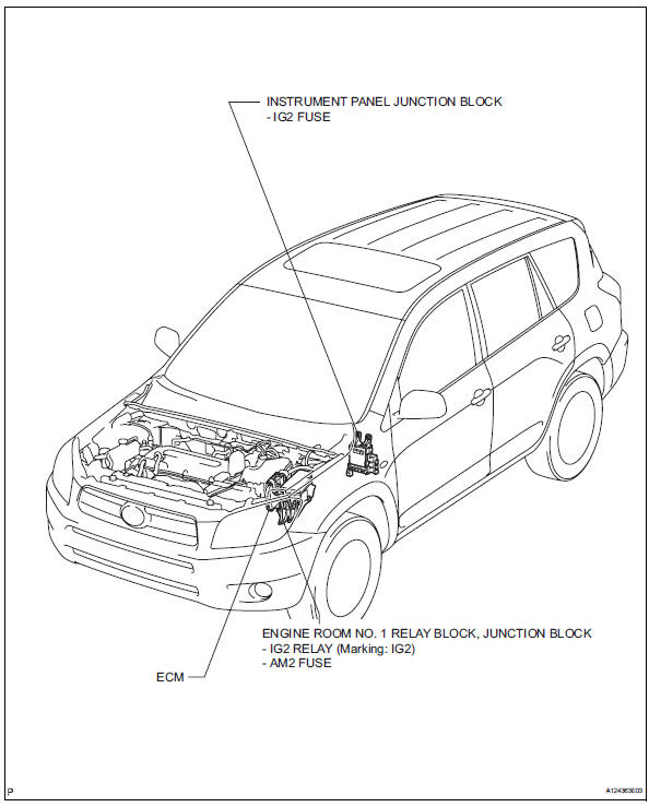
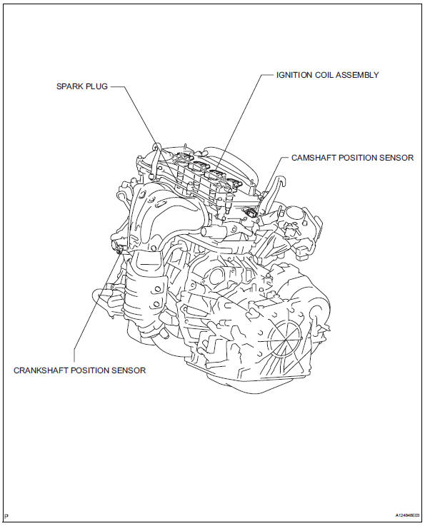
Parts location
System diagram
...
Skid control buzzer circuit
Description
The skid control buzzer sounds while the vsc is activated.
Wiring diagram
Inspection procedure
Notice:
When replacing the abs and traction actuator, perform the zero point
calibration (see page bc-
24).
Check can communication system
Check if the can communication d ...
© 2011-2026 Copyright www.trav4.net
