Toyota RAV4 (XA40) 2013-2018 Service Manual: Problem symptoms table (2006/01- )
Hint:
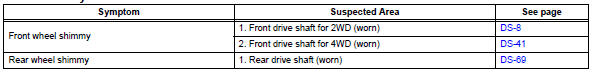
Use the table below to help determine the cause of the problem symptom. The potential causes of the symptoms are listed in order of probability in the "suspected area" column of the table. Check each symptom by checking the suspected areas in the order they are listed. Replace parts as necessary.
Drive shaft system
 Problem symptoms table (2005/11-2006/01)
Hint:
Use the table below to help determine the cause of the
problem symptom. The potential causes of the symptoms are
listed in order of probability in the "suspected area" column of
th ...
 Front drive shaft assembly (for 2wd)
Components (2005/11-2006/01)
Components (2006/01- )
...
Other materials:
Front passenger side seat belt warning light malfunction
Description
When the ignition switch is on, the center airbag sensor transmits front seat
inner belt status signals to
the combination meter through the can bus line. If the front passenger seat belt
is not fastened, the
heater control panel (automatic a/c) or clock (manual a/c) blinks the fr ...
Pressure control solenoid "A" electrical (shift solenoid valve sl1)
Description
Shifting from 1st to o/d is performed in combination with the on and off
operation of the shift solenoid
valves sl1 and sl2, which are controlled by the ecm. If an open or short circuit
occurs in any of the shift
solenoid valves, the ecm controls the remaining normal shift soleno ...
Tire pressure warning light circuit
Description
If the tire pressure warning ecu detects trouble, the tire pressure warning
light turns on and tire pressure
monitor is canceled at the same time. At this time, the ecu records a dtc in
memory.
Connect terminals tc and cg of the dlc3 to make the tire pressure warning light
bli ...
