Toyota RAV4 (XA40) 2013-2018 Service Manual: Problem symptoms table (2005/11-2006/01)
Hint:
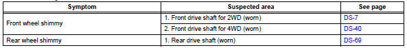
Use the table below to help determine the cause of the problem symptom. The potential causes of the symptoms are listed in order of probability in the "suspected area" column of the table. Check each symptom by checking the suspected areas in the order they are listed. Replace parts as necessary.
Drive shaft system

 Problem symptoms table (2006/01- )
Hint:
Use the table below to help determine the cause of the
problem symptom. The potential causes of the symptoms are
listed in order of probability in the "suspected area" column of
th ...
Other materials:
Seat belt instructions
for canadian owners
(in french)
The following is a french explanation of seat belt instructions
extracted from the seat belt section in this manual.
See the seat belt section for more detailed seat belt instructions in
english.
Utilisation adéquate des ceintures de sécurité
Tirez sur la ceinture &eacut ...
Engine (ignition) switch
(vehicles with smart key
system)
Performing the following
operations when carrying
the electronic key on your
person starts the engine or
changes engine switch
modes.
Starting the engine
1. Pull the parking brake switch
to check that the parking
brake is set.
The parking brake indicator will
come on.
2. Check that the shift lever i ...
Coolant
Replacement
Remove no. 1 Engine under cover
Drain engine coolant
Loosen the radiator drain cock plug.
Hint:
Collect the coolant in a container and dispose of it
according to the regulations in your area.
Remove the radiator reservoir cap.
Caution:
Do not remove the radiator ...
