Toyota RAV4 (XA40) 2013-2018 Service Manual: Transmission range sensor circuit malfunction (prndl input)
Description
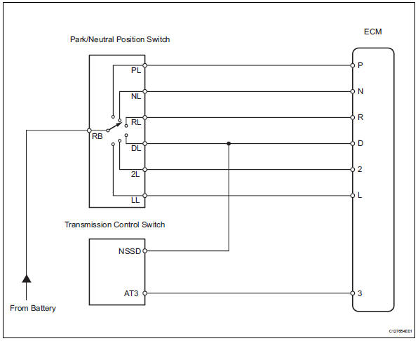
The park/neutral position (pnp) switch detects the shift lever position and sends signals to the ecm.
Monitor description
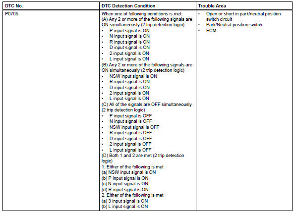
These dtcs indicate a problem with the park/neutral position switch and the wire harness in the park/ neutral position switch circuit.
The park/neutral position switch detects the shift lever position and sends a signal to the ecm.
For security, the park/neutral position switch detects the shift lever position so that the engine can be started only when the shift lever is on p or n.
The park/neutral position switch sends a signal to the ecm according to the shift lever position (r, d, 3, 2 or l).
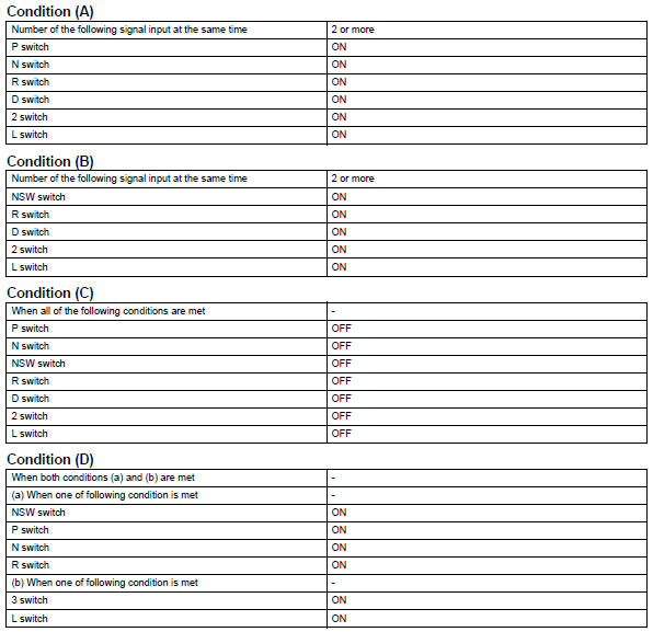
The ecm determines that there is a problem with the switch or related parts if it receives more than 1 position signal simultaneously. The ecm will illuminate the mil and store the dtc.
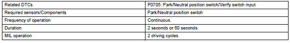
Monitor strategy
![]()
Typical enabling conditions

Typical malfunction thresholds
Component operating range
![]()
Wiring diagram
Inspection procedure
Hint:
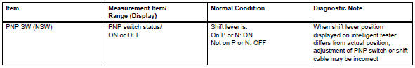
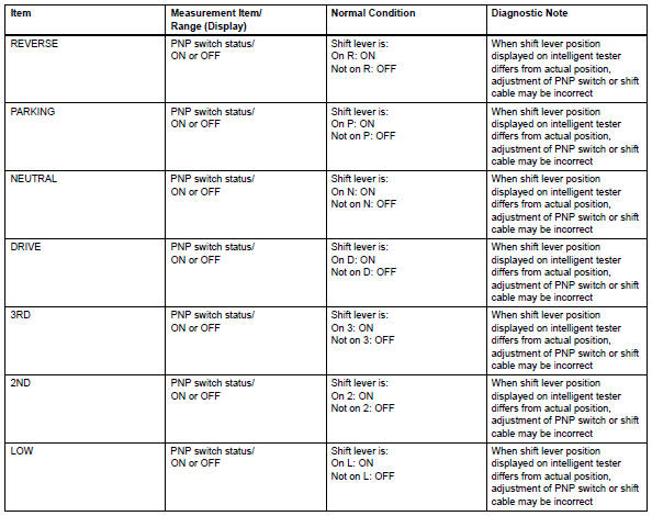
Using the intelligent tester's data list allows switch, sensor, actuator and other item values to be read without removing any parts. Reading the data list early in troubleshooting is one way to save time.
Notice:
In the table below, the values listed under "normal condition" are reference values. Do not depend solely on these reference values when deciding whether a part is faulty or not.
- Warm up the engine.
- Turn the ignition switch off.
- Connect the intelligent tester to the can vim. Then connect the can vim to the dlc3.
- Turn the ignition switch on and turn the tester on.
- Enter the following menus: diagnosis / enhanced obd ii / data list.
- Follow the instructions on the tester and read the data list.
- Check wire harness (park/neutral position switch - battery)
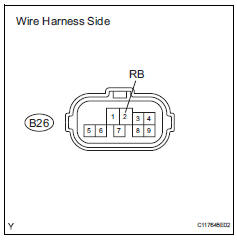
- Disconnect the b26 park/neutral position switch connector.
- Turn the ignition switch on.
- Measure the voltage.
Standard voltage 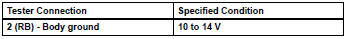

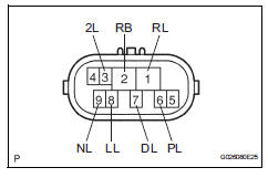
- Inspect park/neutral position switch
- Disconnect the b26 park/neutral position switch connector.
- Measure the resistance of the park/neutral position switch when the shift lever is moved to each position.
Standard resistance 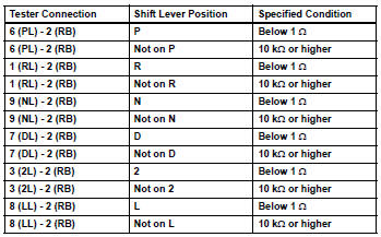

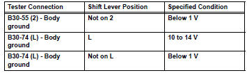
- Check wire harness (ecm - battery and body ground)
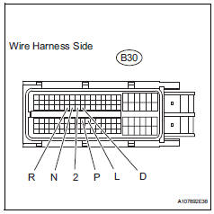
- Disconnect the b30 ecm connector.
- Turn the ignition switch on.
- Measure the voltage of the wire harness side connector.
Standard voltage 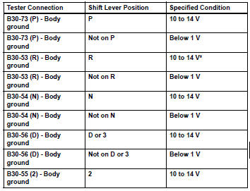
Hint:
*: The voltage will drop slightly due to the illumination of the back-up light.

- Check wire harness (park/neutral position switch - transmission control switch)
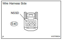
- Disconnect the e40 switch connector.
- Turn the ignition switch on.
- Measure the voltage when the shift lever is moved to each position.
Standard voltage 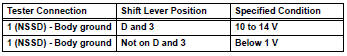

- Inspect transmission control switch
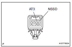
- Disconnect the e40 switch connector.
- Measure the resistance of the switch when the shift lever is moved to each position.
Standard resistance 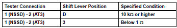

- Check wire harness (transmission control switch - battery and body ground)
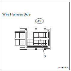
- Disconnect the a9 ecm connector.
- Turn the ignition switch on.
- Measure the voltage of the wire harness side connector.
Standard voltage 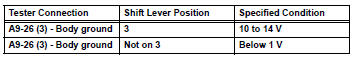
Hint:
*: The voltage will drop slightly due to the illumination of the back-up light.

 Diagnostic trouble code chart
If a dtc is displayed during the dtc check, check the circuit
listed in the table below and proceed to the page given.
Hint:
*1: "Comes on" means the malfunction indicator lamp
(mil) ...
 Transmission fluid temperature sensor "A" circuit
Description
The automatic transmission fluid (atf) temperature sensor converts the atf
temperature into a
resistance value which is input into the ecm.
The ecm applies a voltage to the temp ...
Other materials:
Driving information display
â– Drive information
2 items that are selected using
the "Drive Info Items" setting
(average speed and distance)
can be displayed vertically.
Use the displayed information as a
reference only.
"Average Speed": Displays
the average vehicle speed
since engine start*
"Distance": Displays the dist ...
Removal
Drain differential oil
Remove rear wheel
Remove tailpipe assembly
Remove the tailpipe (see page ex-2).
Remove center exhaust pipe assembly
Remove the center pipe (see page ex-2).
Remove propeller with center bearing
shaft assembly (see page pr-3)
Remove rear suspen ...
Disassembly
Fix differential carrier sub-assembly
Fix the rear differential carrier in place with the
overhaul attachment.
Remove stud bolt
Remove the 4 stud bolts from the transmission
coupling.
Remove differential drain plug
Using a 10 mm socket hexagon wrench, remove ...
