Toyota RAV4 (XA40) 2013-2018 Service Manual: Transmission fluid temperature sensor "A" circuit
Description
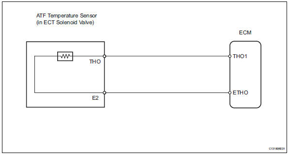
The automatic transmission fluid (atf) temperature sensor converts the atf temperature into a resistance value which is input into the ecm.
The ecm applies a voltage to the temperature sensor through ecm terminal tho1.
The sensor resistance changes with the atf temperature.
One terminal of the sensor is grounded so that the sensor resistance and voltage decrease as the temperature becomes higher.
The ecm calculates the atf based on the voltage signal.
Monitor description
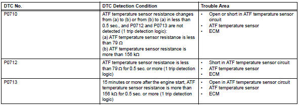
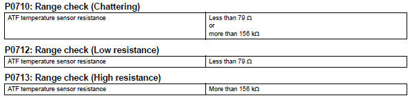
Atf temperature sensor converts atf temperature to an electrical resistance value. Based on the resistance, the ecm determines the atf temperature, and the ecm detects an open or short in the atf temperature circuit. If the resistance value of the atf temperature is less than 79 ù*1 or more than 156 kù*2, the ecm interprets this as a fault in the atf sensor or wiring. The ecm will illuminate the mil and store the dtc.
Hint:
- *1: 150°C (302°f) or more is indicated regardless of the actual atf temperature.
- *2: -40°C (-40°f) is indicated regardless of the actual atf temperature.
- The atf temperature can be checked on the intelligent tester display.
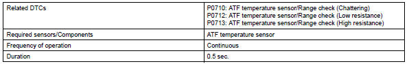
Monitor strategy
![]()
Typical enabling conditions
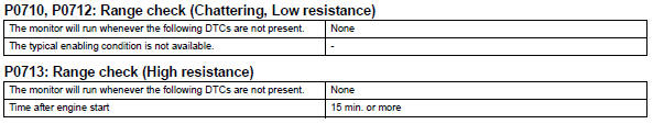
Typical malfunction thresholds
Component operating range
![]()
Wiring diagram
Inspection procedure
Hint:
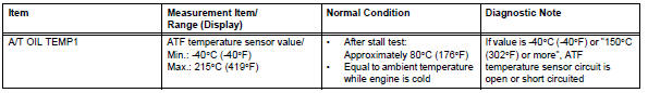
Using the intelligent tester's data list allows switch, sensor, actuator and other item values to be read without removing any parts. Reading the data list early in troubleshooting is one way to save time.
Notice:
In the table below, the values listed under "normal condition" are reference values. Do not depend solely on these reference values when deciding whether a part is faulty or not.
- Warm up the engine.
- Turn the ignition switch off.
- Connect the intelligent tester to the can vim. Then connect the can vim to the dlc3
- Turn the ignition switch on and turn the tester on.
- Enter the following menus: diagnosis / enhanced obd ii / data list.
- Follow the instructions on the tester and read the data list.
Hint:
- When dtc p0712 is output and the tester output is 150°c (302°f) or more, there is a short circuit.
- When dtc p0713 is output and the tester output is -40°c (-40°f), there is an open circuit.
Measure the resistance between terminal tho1 (tho) and the body ground.

Hint:
If a circuit related to the atf temperature sensor becomes open, p0713 is set in approximately 0.5 Seconds. It is not necessary to inspect the circuit when p0711 is set
- Inspect transmission wire (atf temperature sensor)
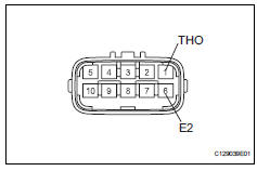
- Disconnect the b27 wire connector.
- Measure the resistance of the transmission wire.
Standard resistance 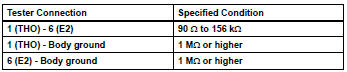
Hint:
If the resistance is out of the specified range of either of the atf temperatures shown in the table below, the driveability of the vehicle may decrease.
Standard resistance 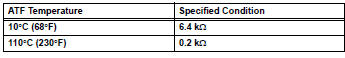


- Check wire harness (transmission wire - ecm)
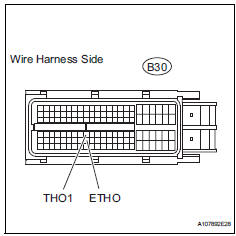
- Disconnect the b30 ecm connector.
- Measure the resistance of the wire harness side connector.
Standard resistance 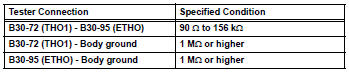

Replace ecm
 Transmission range sensor circuit malfunction (prndl input)
Description
The park/neutral position (pnp) switch detects the shift lever position and
sends signals to the ecm.
Monitor description
These dtcs indicate a problem with the park/neutral p ...
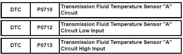
 Transmission fluid temperature sensor "A" performance
Description
Refer to dtc p0710 (see page ax-46).
Monitor description
This dtc indicates that there is a problem with output from the atf
temperature sensor and that the
sensor itself is ...
Other materials:
Exhaust pipe
Components
Removal
Disconnect cable from negative battery terminal
Caution:
Wait at least 90 seconds after disconnecting the
cable from the negative (-) battery terminal to
prevent airbag and seat belt pretensioner activation.
Remove heated oxygen sensor (for bank 1
sensor 2) (s ...
The rear cross traffic alert function
The rear cross traffic alert functions when your vehicle is in reverse.
It can detect other vehicles approaching from the right or left rear of
the vehicle. It uses radar sensors to alert the driver of the other vehicle’s
existence through flashing the outside rear view mirror indicators
and ...
Battery temperature sensor circuit
Description
The battery temperature sensor installed on the battery current sensor
detects battery temperature.
A thermistor is integrated into the battery temperature sensor, and the
resistance in the battery
temperature sensor changes according to the battery temperature.
The r ...
