Toyota RAV4 (XA40) 2013-2018 Service Manual: Transmission fluid temperature sensor "A" performance
Description
Refer to dtc p0710 (see page ax-46).
Monitor description
This dtc indicates that there is a problem with output from the atf temperature sensor and that the sensor itself is defective. The atf temperature sensor converts the atf temperature to an electrical resistance value. Based on the resistance, the ecm determines the atf temperature, detects open or short circuits of the atf temperature circuit, and detects faults in the atf temperature sensor.
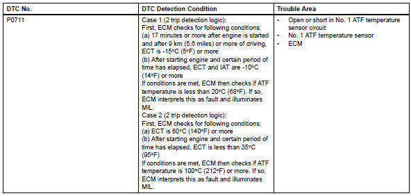
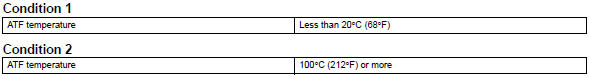
Case 1 (2 trip detection logic): first, the ecm checks for the following conditions:
- 17 Minutes or more after the engine is started and after 9 km (5.6 Miles) or more of driving, the ect is -15ÂḞc (5ÂḞf) or more.
- After starting the engine and a certain period of time has elapsed, the ect and iat are -10ÂḞc (14ÂḞf) or more.
If the conditions are met, the ecm then checks if the atf temperature is less than 20ÂḞc (68ÂḞf). If so, the ecm interprets this as a fault and illuminates the mil.
Case 2 (2 trip detection logic): first, the ecm checks for the following conditions: (a)ect is 60ÂḞc (140ÂḞf) or more.
(B)after starting the engine and a certain period of time has elapsed, the ect is less than 35ÂḞc (95ÂḞf).
If the conditions are met, the ecm then checks if the atf temperature is 100ÂḞc (212ÂḞf) or more. If so, the ecm interprets this as a fault and illuminates the mil.
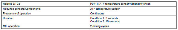
Monitor strategy
![]()
Typical enabling conditions
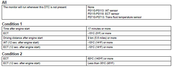
Typical malfunction thresholds
Component operating range
![]()
Wiring diagram
Refer to dtc p0710 (see page ax-47).
Inspection procedure
Hint:
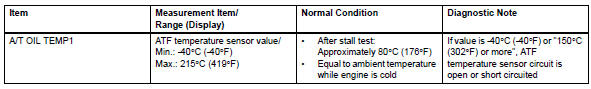
Using the intelligent tester's data list allows switch, sensor, actuator and other item values to be read without removing any parts. Reading the data list early in troubleshooting is one way to save time.
Notice:
In the table below, the values listed under "normal condition" are reference values. Do not depend solely on these reference values when deciding whether a part is faulty or not.
- Warm up the engine.
- Turn the ignition switch off.
- Connect the intelligent tester to the can vim. Then connect the can vim to the dlc3.
- Turn the ignition switch on and turn the tester on.
- Enter the following menus: diagnosis / enhanced obd ii / data list.
- Follow the instructions on the tester and read the data list.
Hint:
- When dtc p0712 is output and the tester output is 150ÂḞc (302ÂḞf) or more, there is a short circuit.
- When dtc p0713 is output and the tester output is -40ÂḞc (-40ÂḞf), there is an open circuit.
Measure the resistance between terminal tho1 (tho) and the body ground.

Hint:
If a circuit related to the atf temperature sensor becomes open, p0713 is set in approximately 0.5 Seconds.
It is not necessary to inspect the circuit when p0711 is set.
- Check other dtc output (in addition to dtc p0711)
- Connect the intelligent tester to the can vim. Then connect the can vim to the dlc3.
- Turn the ignition switch on and turn the tester on.
- Enter the following menus: diagnosis / enhanced obd ii / dtc info / current codes.
- Read the dtcs using the tester.
Result 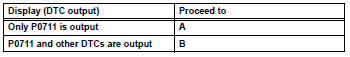
Hint:
If any other codes besides p0711 are output, perform troubleshooting for those dtcs first.

- Check transaxle fluid level
Ok: automatic transaxle fluid level is correct.

Repair or replace transmission wire
 Transmission fluid temperature sensor "A" circuit
Description
The automatic transmission fluid (atf) temperature sensor converts the atf
temperature into a
resistance value which is input into the ecm.
The ecm applies a voltage to the temp ...
 Input speed sensor circuit no signal
Description
This sensor detects the rotation speed of the turbine, which shows the input
revolution of the transaxle. By
comparing the input speed signal (nt) with the counter gear speed sens ...
Other materials:
Removal
Hint:
Use the same procedures for the rh side and lh side.
The procedures listed below are for the rh side.
Remove front seat headrest assembly
Remove front seat assembly
Operate the power seat switch knob and move the
seat to the foremost position.
Using a screwdriver, d ...
General maintenance (2005/11-2006/01)
Inspect steering linkage and gear housing
Check the steering wheel free play.
Check the steering linkage for looseness or
damage.
Check that the tie rod ends do not have
excessive play
Check that the dust seals and boots are not
damaged.
Check that the boot clamps are not ...
Air inlet control servo motor
Components
Removal
Remove blower assembly
Remove the blower (see page ac-203).
Remove air inlet control servo motor (see
page ac-210)
Inspection
Inspect air inlet control servo motor (for automatic air conditioning
system)
Inspect the servo motor operation. ...
