Toyota RAV4 (XA40) 2013-2018 Service Manual: Removal
Hint:
- Use the same procedures for the lh side and rh side.
- The procedures listed below are for the lh side.
- Disconnect cable from negative battery terminal
Caution:
Wait at least 90 seconds after disconnecting the cable from the negative (-) battery terminal to prevent airbag and seat belt pretensioner activation.
- Remove front door scuff plate lh (see page ir-26)
- Remove front door opening trim weatherstrip lh
- Remove rear door scuff plate lh (see page ir-29)
- Remove rear door opening trim weatherstrip lh
- Remove center pillar garnish lower lh
- Remove the lap belt anchor cover.
- Remove the anchor's built-in bolt from the pillar and disconnect the outer belt.
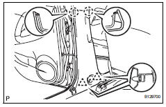
- Using a screwdriver, detach the 2 claws.
Hint:
Tape the screwdriver tip before use.
- Using a clip remover, detach the 2 clips and remove the garnish.
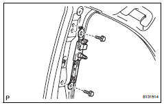
- Remove center pillar garnish lh
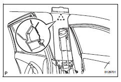
- Using a screwdriver, remove the 2 screws.
- Using a clip remover, detach the clip then remove the garnish.
- Pull out the outer belt anchor from the center pillar garnish.
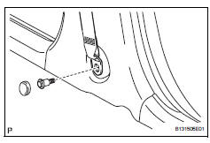
- Remove front seat outer belt assembly lh
- Remove the nut and disconnect the shoulder anchor.
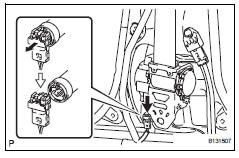
- Disconnect the pretensioner connector as shown in the illustration.
- Remove the bolt and outer belt.
- Remove front shoulder belt anchor plate sub-assembly lh
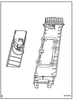
- Using a screwdriver, detach the 6 claws.
- Remove the anchor plate from the garnish.
Hint:
Tape the screwdriver tip before use.
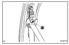
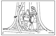
- Remove front shoulder belt anchor adjuster assembly
- Remove the 2 bolts and anchor.
 Precaution
Caution:
Replace the faulty parts of the seat belt systems (outer
belt, inner belt, bolts, nuts, adjustable shoulder anchor,
tether anchor hardware and other related parts). When
inspecting a ...
 Inspection
Inspect front seat outer belt assembly
Notice:
Do not disassemble the retractor.
Before installing the outer belt, check the elr.
When the inclination of the retractor is 15Đ or
...
Other materials:
Wireless remote control
Function summary
The wireless remote control can be used to lock and unlock the vehicle.
It also opens and closes the back door.
Vehicles without a smart key system
Locks all the doors
Unlocks all the doors
Pressing the button unlocks the
driver’s door. Pressing the button
again wi ...
Position initialization incomplete
Description
This dtc is output when the sliding roof drive gear (sliding roof ecu) has
not been initialized.
Wiring diagram
Refer to dtc b2341 (see page rf-11).
Inspection procedure
Initialize sliding roof drive gear sub-assembly (sliding roof ecu)
Check that the sliding roof ...
Installation
Replace roof carrier seal
Remove the seals.
Install new seals as shown in the illustration.
Install roof rack leg front lh
Install the leg cushion front.
Install the roof rack leg front with the 2 screws.
Torque: 2.8 To 5.0 N*m (29 to 51 kgf*cm, 25 to 44
in.*Lbf)
...
