Toyota RAV4 (XA40) 2013-2018 Service Manual: Diagnostic trouble code chart
Hint:
- If no abnormality is found when inspecting parts, check the skid control ecu and check for poor contact at the ground points.
- If a dtc is displayed during the dtc check, check the circuit for the dtc listed in the table below. For details of each dtc, refer to the page indicated.
- When 2 or more dtcs are detected, perform circuit inspections one by one until the problem is identified.
- All dtcs in the table below are detected in accordance with 1 trip detection logic.
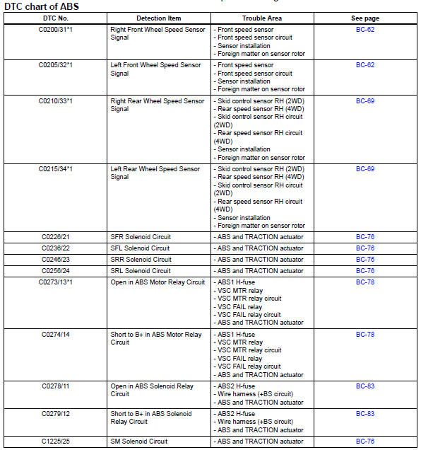
Even after the trouble areas are repaired, the abs warning light will not go off unless the following operations are performed.
- *1:
- Drive the vehicle at 20 km/h (12 mph) for 30 seconds or more and check that the abs warning light goes off.
- Clear the dtc(s).
- *2:
- Keep the vehicle stationary for 5 seconds or more and depress the brake pedal lightly 2 or 3 times.
- Drive the vehicle at a vehicle speed of 50 km/h (31 mph) and keep depressing the brake pedal firmly for approximately 3 seconds.
- Repeat the above operation 3 times or more and check that the abs warning light goes off.
- Clear the dtc(s).
- *3: 16-Inch disc
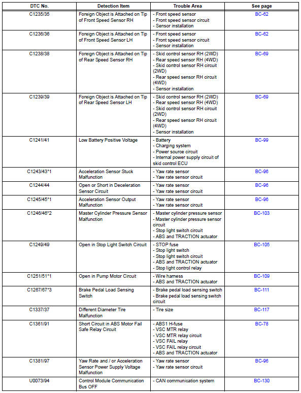
Hint:
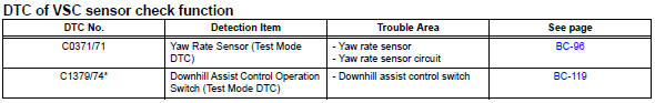
*: W/ downhill assist control
Description
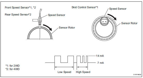
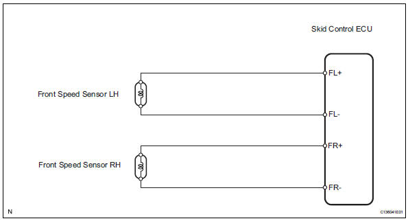
The speed sensors detect the wheel speeds and send appropriate signals to the skid control ecu.
Speed sensor rotors have rows of alternating n and s magnetic poles, and their magnetic fields change as the rotors turn.
The speed sensors detect those magnetic changes and send pulse signals to the skid control ecu. The ecu monitors the wheel speeds through these pulse signals to control the abs control system.
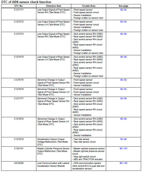
Dtcs c1271/71, c1272/72, c1275/75 and c1276/76 can be deleted when the speed sensor sends a vehicle speed signal or the test mode ends. Dtcs c1271/71, c1272/72, c1275/75/75 and c1276/76 are output only in the test mode.
Hint:
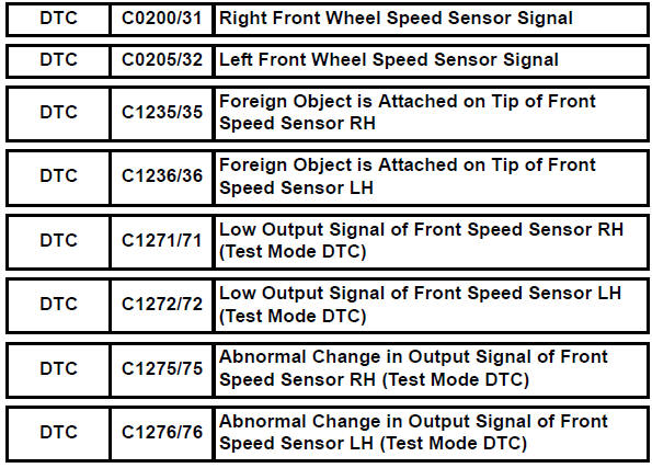
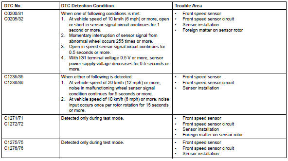
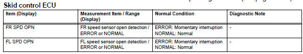
- Dtcs c0200/31 and c1235/35 relate to the front speed sensor rh.
- Dtcs c0205/32 and c1236/36 relate to the front speed sensor lh.
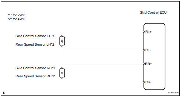
Wiring diagram
Inspection procedure
Notice:
Check the speed sensor signal in test mode after cleaning or replacement (see page bc-28).
- Check harness and connector (momentary interruption)
- Using the data list of the intelligent tester, check for any momentary interruption in the wire harness and connector corresponding to a dtc (see page bc-23).
Ok: there are no momentary interruptions.
Hint:
Perform the above inspection before removing the sensor and connector.

- Read value of data list (front speed sensor)
- Check the data list for proper functioning of the front speed sensor.
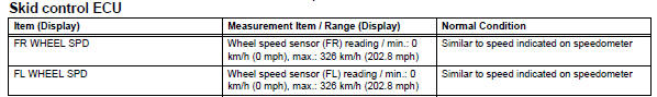
Ok: there is almost no difference between actual wheel speed and displayed speed value.
Hint:
There is a tolerance of +-10% in the speedometer indication.


- Perform test mode inspection (signal check)
- Perform a test mode inspection and check for dtcs (see page bc-28).
Ok: no dtc output.

- Reconfirm dtc
- Clear the dtc(s) (see page bc-47).
- Start the engine.
- Drive the vehicle at a speed of 20 km/h (12 mph) or more for at least 60 seconds.
- Check if the same dtc(s) is output (see page bc-47).

- Inspect front speed sensor (installation)
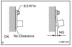
- Check that the speed sensor installation bolt is tightened properly.
Ok: the installation bolt is tightened properly, and there is no clearance between the sensor and front steering knuckle.
Torque: 8.5 N*m (87 kgf*cm, 75 in.*Lbf)
Hint:
If the installation portion of the sensor is dirty, clean it and reinstall the sensor.
Check the speed sensor after the speed sensor replacement (see page bc-28).

- Check speed sensor (tip)
- Remove the front speed sensor.
- Check the sensor tip.
Ok: no scratches or foreign matter on the sensor tip.
Hint:
Check the speed sensor signal after the speed sensor clearing or replacement (see page bc-28).

- Check wire harness (skid control ecu - front speed sensor)
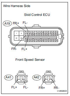
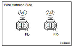
- Disconnect the a19 ecu connector.
- Disconnect the a41 and a42 sensor connectors.
- Measure the resistance of the wire harness side connectors.
Standard resistance:
For lh 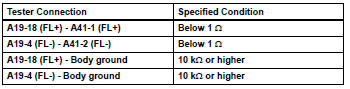
For rh 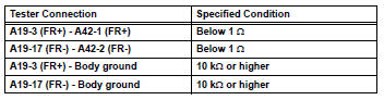

- Check skid control ecu (sensor input voltage)
- Disconnect the a41 and a42 sensor connectors.
- Measure the voltage of the wire harness side connector.
Standard voltage 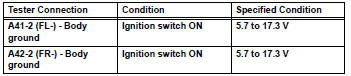

- Reconfirm dtc
- Clear the dtc(s) (see page bc-47).
- Start the engine.
- Drive the vehicle at a speed of 20 km/h (12 mph) or more for at least 60 seconds.
- Check if the same dtc(s) is output (see page bc-47).
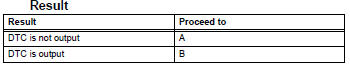
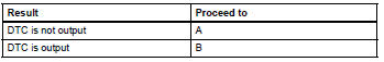
Result 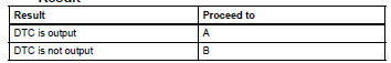

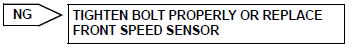
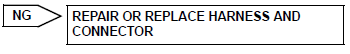
- Replace front speed sensor
- Replace the front speed sensor.

- Reconfirm dtc
- Clear the dtc(s) (see page bc-47).
- Start the engine.
- Drive the vehicle at a speed of 20 km/h (12 mph) or more for at least 60 seconds.
- Check if the same dtc(s) is output (see page bc-47).
Result 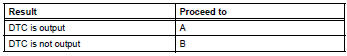

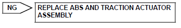
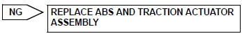
Replace abs and traction actuator assembly
Description
Refer to dtc c0200/31 (see page bc-62).
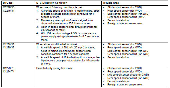
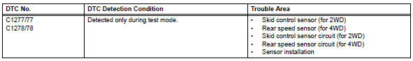
Dtcs c1273/73, c1274/74, c1277/77 and c1278/78 can be deleted when the speed sensor sends a vehicle speed signal or the test mode ends. Dtcs c1273/73, c1274/74, c1277/77 and c1278/78 are output only in the test mode.
Hint:
- Dtc c0210/33 and c1238/38 relate to the skid control sensor rh.
- Dtc c0215/34 and c1239/39 relate to the skid control sensor lh.
Wiring diagram
Inspection procedure
Notice:
Check the speed sensor signal in test mode after cleaning or replacement (see page bc-28).
- Check harness and connector (momentary interruption)
- Using the data list of the intelligent tester, check for any momentary interruption in the wire harness corresponding to a dtc (see page bc-23).
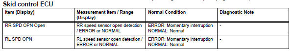
Ok: there are no momentary interruptions.
Hint:
Perform this inspection before removing the sensor and connector.

- Read value of intelligent tester (rear speed sensor)
- Check the data list for proper functioning of the rear speed sensor.
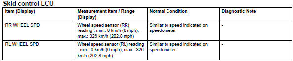
Ok: there is almost no difference between actual wheel speed and displayed speed value.
Hint:
There is a tolerance of +-10% in the speedometer indication.

- Perform test mode inspection (signal check)
- Perform a test mode inspection and check for dtcs (see page bc-28).
Ok: no dtcs output.

- Reconfirm dtc
- Clear the dtc(s) (see page bc-47).
- Start the engine.
- Drive the vehicle at a speed of 20 km/h (12 mph) or more for at least 60 seconds.
- Check if the same dtc(s) is output (see page bc-47).
Result

End
- Inspect skid control sensor or rear speed sensor (installation)
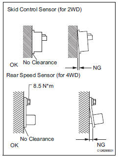
- Check the speed sensor installation.
Ok: for 2wd
There is no clearance between the sensor and rear axle carrier.
For 4wd
The installation bolt is tightened properly and there is no clearance between the sensor and rear axle carrier.
Torque: 8.5 N*m (87 kgf*cm, 75 in.*Lbf)
Hint:
Check the speed sensor signal after the replacement (see page bc-28).

- Check skid control sensor or rear speed sensor (tip)
- Remove the skid control sensor (for 2wd) or rear speed sensor (for 4wd).
- Check the sensor tip.
Ok: no scratches or foreign matter on the sensor tip.

- Check wire harness (skid control ecu - rear speed sensor)
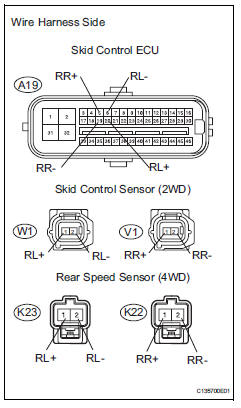
- Disconnect the a19 ecu connector.
- Disconnect w1 and v1 sensor connectors for 2wd.
Disconnect k23 and k22 sensor connectors for 4wd.
- Measure the resistance of the wire harness side connectors.
Standard resistance:
For 2wd (lh side) 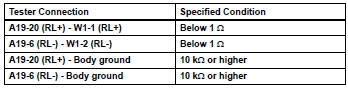
For 2wd (rh side) 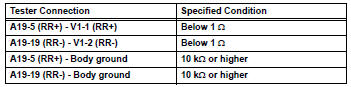
For 4wd (lh side) 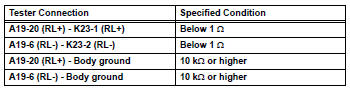
For 4wd (rh side) 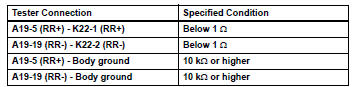

- Check skid control ecu (sensor input voltage)
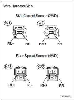
- Disconnect the w1 and v1 sensor connectors for 2wd.
Disconnect the k23 and k22 sensor connectors for 4wd.
- Measure the voltage of the wire harness side connectors.
Standard voltage:
For 2wd 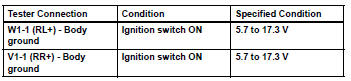
For 4wd 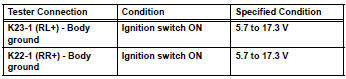

- Reconfirm dtc
- Clear the dtc(s) (see page bc-47).
- Start the engine.
- Drive the vehicle at a speed of 20 km/h (12 mph) or more for at least 60 seconds.
- Check if the same dtc(s) is output (see page bc-47).
Result 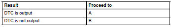

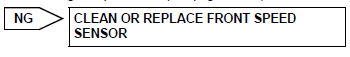
- Replace skid control sensor or rear speed sensor
- Replace the skid control sensor (2wd) or rear speed sensor (4wd).

- Reconfirm dtc
- Clear the dtc(s) (see page bc-47).
- Start the engine.
- Drive the vehicle at a speed of 20 km/h (12 mph) or more for at least 60 seconds.
- Check if the same dtc(s) is output (see page bc-47).
Result 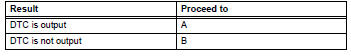


Replace abs and traction actuator assembly
 Data list / active test
Read data list
Hint:
Using the intelligent tester's data list allows switch,
sensor, actuator and other item values to be read without
out removing any parts. Reading the data list early in
...
 Solenoid circuit
Description
This solenoid is turned on in accordance with signals from the skid control
ecu and controls the pressure
on the wheel cylinders to control the braking force.
The solenoid and s ...
Other materials:
Outside rear view mirrors
The rear view mirror's position
can be adjusted to
enable sufficient confirmation
of the rear view.
â– When using the outside rear
view mirrors in a cold weather
When it is cold and the outside rear
view mirrors are frozen, it may not
be possible to fold/extend them or
adjust the mirror surface. Rem ...
Engine coolant temperature circuit range / performance problem
Description
Refer to dtc p0115 (see page es-105).
Monitor description
Engine coolant temperature (ect) sensor cold start monitor
When a cold engine start is performed and then the engine is warmed up, if
the ect sensor value does
not change, it is determined that a malfunction has occ ...
Installation
Hint:
Use the same procedures for the lh side and rh side.
The procedures listed below are for the lh side.
A bolt without a torque specification is shown in the
standard bolt chart (see page ss-2).
Install rear no. 1 Seat outer belt assembly lh
Align the claws with the sea ...
