Toyota RAV4 (XA40) 2013-2018 Service Manual: Short to b+ in can bus line
Description
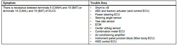
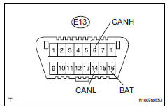
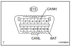
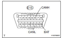
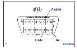
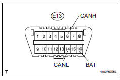
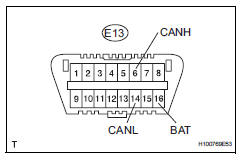
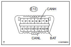
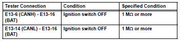
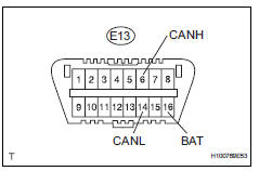
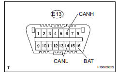
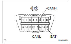
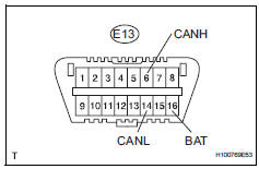
There may be a short circuit between the can bus line and +b when there is resistance between terminals 6 (canh) and 16 (bat) or terminals 14 (canl) and 16 (bat) of the dlc3.
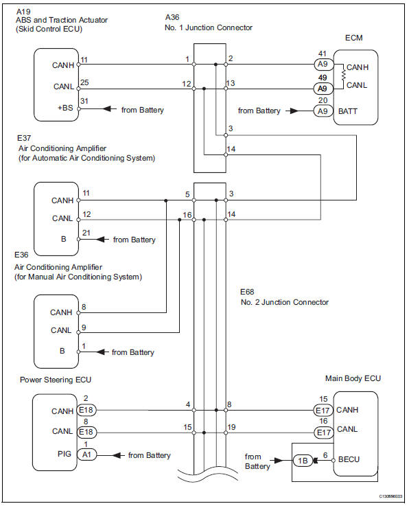
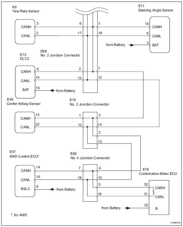
Wiring diagram
Inspection procedure
Notice:
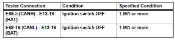
- Turn the ignition switch off before measuring the resistances of the main wire and the branch wire.
- After the ignition switch is turned off, check that the key reminder warning system and light reminder warning system are not in operation.
- Before measuring the resistance, leave the vehicle for at least 1 minute and do not operate the ignition switch, any switches or doors. If doors need to be opened in order to check connectors, open the doors and leave them open.
Hint:
Operating the ignition switch, any switches or any doors triggers related ecu and sensor communication with the can, which causes resistance variation.
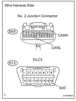
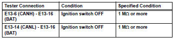
- Check can bus line for short to +b (dlc3 branch wire)
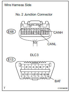
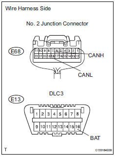
- Disconnect the e68 no. 2 Junction connector.
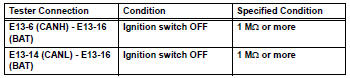
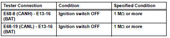
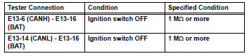
- Measure the resistance of the dlc3.
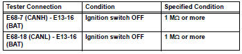
Standard resistance 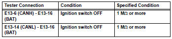

- Connect connector
- Reconnect the e68 no. 2 Junction connector.

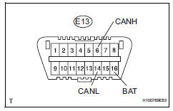
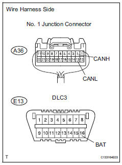
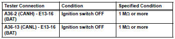
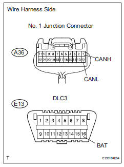
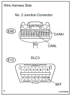
- Check can bus line for short to +b (no. 1 Junction connector side)
- Disconnect the a36 no. 1 Junction connector.
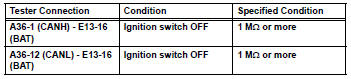
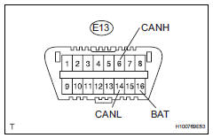
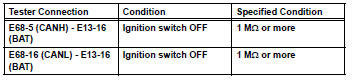
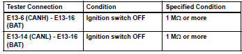
- Measure the resistance of the dlc3.
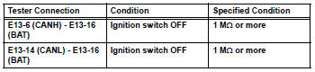
Standard resistance

- Connect connector
- Reconnect the a36 no. 1 Junction connector.

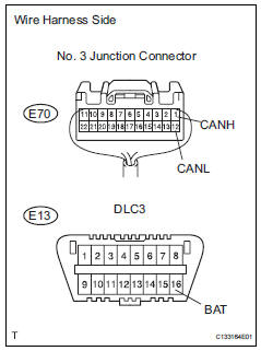
- check can bus line for short to +b (no. 3 junction connector, no. 4 junction connector side)
- Disconnect the e70 no. 3 Junction connector.
- Measure the resistance of the dlc3.
Standard resistance 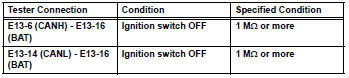


- Connect connector
- Reconnect the e70 no. 3 Junction connector.

- Check can bus line for short to +b (no. 4 Junction connector side)
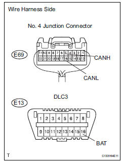
- Disconnect the e69 no. 4 Junction connector.
- Measure the resistance of the dlc3.
Standard resistance

- Connect connector
- Reconnect the e69 no. 4 Junction connector.

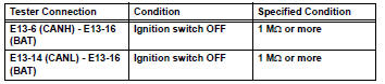
- Check can bus line for short to +b (no. 3 Junction connector - center airbag sensor assembly)
- Disconnect the e70 no. 3 Junction connector.
- Measure the resistance of the wire harness side connectors.
Standard resistance

- Connect connector
- Reconnect the e70 no. 3 Junction connector.

- Check can bus line for short to +b (center airbag sensor assembly)
- Disconnect the e45 center airbag sensor connector.
- Measure the resistance of the dlc3.
Standard resistance

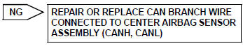
Replace center airbag sensor assembly
- Check can bus line for short to +b (no. 1 Junction connector - ecm)
- Disconnect the a36 no. 1 Junction connector.
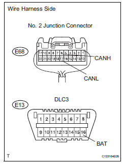
- Measure the resistance of the wire harness side connectors.
Standard resistance

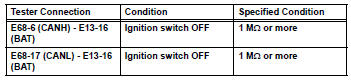
- Check can bus line for short to +b (no. 1 Junction connector - abs and traction actuator)
- Measure the resistance of the wire harness side connectors.
Standard resistance

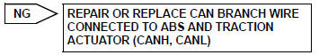
Repair or replace can main wire and connector (no. 1 Junction connector - no.
2 Junction connector)
- Connect connector
- Reconnect the a36 no. 1 Junction connector.

- Check can bus line for short to +b (ecm)
- Disconnect the a9 ecm connector.
- Measure the resistance of the dlc3.
Standard resistance

Replace ecm
- Connect connector
- Reconnect the a36 no. 1 Junction connector.

- Check can bus line for short to +b (abs and traction actuator)
- Disconnect the a19 abs and traction actuator (skid control ecu) connector.
- Measure the resistance of the dlc3.
Standard resistance
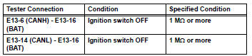

Replace abs and traction actuator (skid control ecu)
- Connect connector
- Reconnect the e70 no. 3 Junction connector.

- Check can bus line for short to +b (no. 2 Junction connector - yaw rate sensor)
- Disconnect the e68 no. 2 Junction connector.
- Measure the resistance of the wire harness side connectors.
Standard resistance

- Check can bus line for short to +b (no. 2 Junction connector - power steering ecu)
- Measure the resistance of the wire harness side connectors.
Standard resistance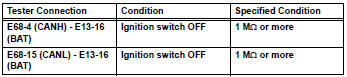

- Check can bus line for short to +b (no. 2 Junction connector - main body ecu)
- Measure the resistance of the wire harness side connectors.
Standard resistance


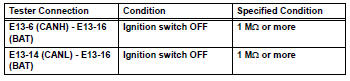
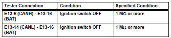
- Check can bus line for short to +b (no. 2 Junction connector - air conditioning amplifier)
- Measure the resistance of the wire harness side connectors.
Standard resistance

- Check can bus line for short to +b (no. 2 Junction connector - steering angle sensor)
- Measure the resistance of the wire harness side connectors.
Standard resistance


Repair or replace can main wire and connector (no. 2 Junction connector - no.
3 Junction connector)
- Connect connector
- Reconnect the e68 no. 2 Junction connector.

- Check can bus line for short to +b (yaw rate sensor)

- Disconnect the k6 yaw rate sensor connector.
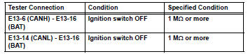
- Measure the resistance of the dlc3.
Standard resistance

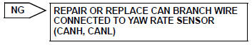
Replace yaw rate sensor
- Connect connector
- Reconnect the e68 no. 2 Junction connector.

- Check can bus line for short to +b (power steering ecu)
- Disconnect the e18 power steering ecu connector.
- Measure the resistance of the dlc3.
Standard resistance

Replace power steering ecu
- Connect connector
- Reconnect the e68 no. 2 Junction connector.

- Check can bus line for short to +b (main body ecu)
- Disconnect the e17 main body ecu connector.
- Measure the resistance of the dlc3.
Standard resistance

Replace instrument panel junction block (main body ecu)
- Connect connector
- Reconnect the e68 no. 2 Junction connector.

- Check can bus line for short to +b (air conditioning amplifier)
- Disconnect the e37*1 or e36*2 air conditioning amplifier connector.
Hint:
- *1: For automatic air conditioning system.
- *2: For manual air conditioning system.
- Measure the resistance of the dlc3.
Standard resistance

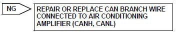
Replace air conditioning amplifier
- Connect connector
- Reconnect the e68 no. 2 Junction connector.

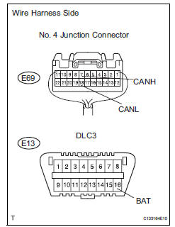
- Check can bus line for short to +b (steering angle sensor)
- Disconnect the e11 steering sensor connector.
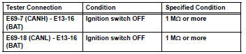
- Measure the resistance of the dlc3.
Standard resistance

Replace steering angle sensor
- Check can bus line for short to +b (no. 4 Junction connector - 4wd control ecu)
Notice:
For vehicles without 4wd, go to "check can bus line for short to +b (no. 4 Junction connector - combination meter ecu)".
- Measure the resistance of the wire harness side connectors.
Standard resistance

- Check can bus line for short to +b (no. 4 Junction connector - combination meter ecu)
- measure the resistance of the wire harness side connectors.
Standard resistance

- Connect connector
- Reconnect the e69 no. 4 Junction connector.

- Check can bus line for short to +b (4wd control ecu)
- Disconnect the e57 4wd control ecu connector.
- Measure the resistance of the dlc3.
Standard resistance

Replace 4wd control ecu
- Connect connector
- Reconnect the e69 no. 4 Junction connector.

- Check can bus line for short to +b (combination meter ecu)
- Disconnect the e19 combination meter ecu connector.
- Measure the resistance of the dlc3.
Standard resistance

Replace combination meter ecu
 Short in can bus lines
Description
There may be a short circuit between the can bus lines when the resistance
between terminals 6 (canh)
and 14 (canl) of the dlc3 is below 54
.
Wiring diagram
Inspection ...
 Short to gnd in can bus line
(2005/11-2006/01)
Description
There may be a short circuit between the can bus line and gnd when there is
resistance between
terminals 6 (canh) and 4 (cg) or terminals 14 (canl) and 4 (cg) of the ...
Other materials:
Installation
Hint:
Use the same procedures for the rh side and lh side.
The procedures listed below are for the lh side.
When replacing the clip, heat the clip and body using a
heat light.
Standard heating temperature
Notice:
Do not heat the clip and vehicle body excessively.
Replace roof dri ...
Changing settings of the
pre-collision system
â– Enabling/disabling the pre-collision
system
The pre-collision system can be
enabled/disabled on the
screen of the
multi-information display.
The system is automatically
enabled each time the engine
switch is turned to ON.
If the system is disabled, the
PCS warning light will turn on
and a mes ...
Terminals of ecu
Check occupant classification ecu
Measure the voltage of the connector.
...
