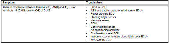
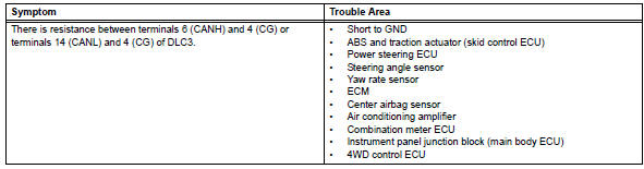
Toyota RAV4 (XA40) 2013-2018 Service Manual: Short to gnd in can bus line
(2005/11-2006/01)
Description
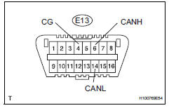
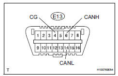
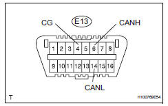
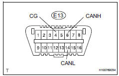
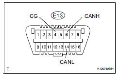
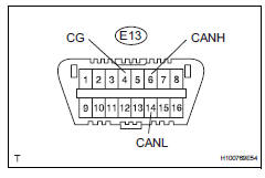
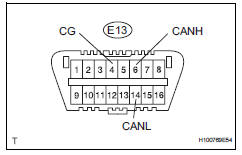
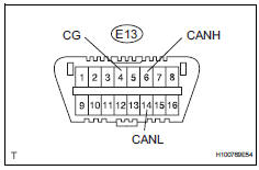
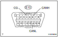
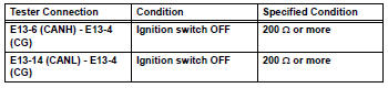
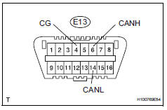
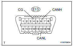
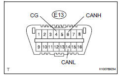
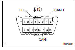
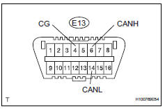
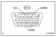
There may be a short circuit between the can bus line and gnd when there is resistance between terminals 6 (canh) and 4 (cg) or terminals 14 (canl) and 4 (cg) of the dlc3.
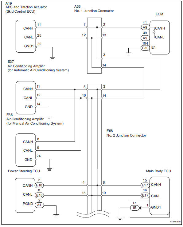
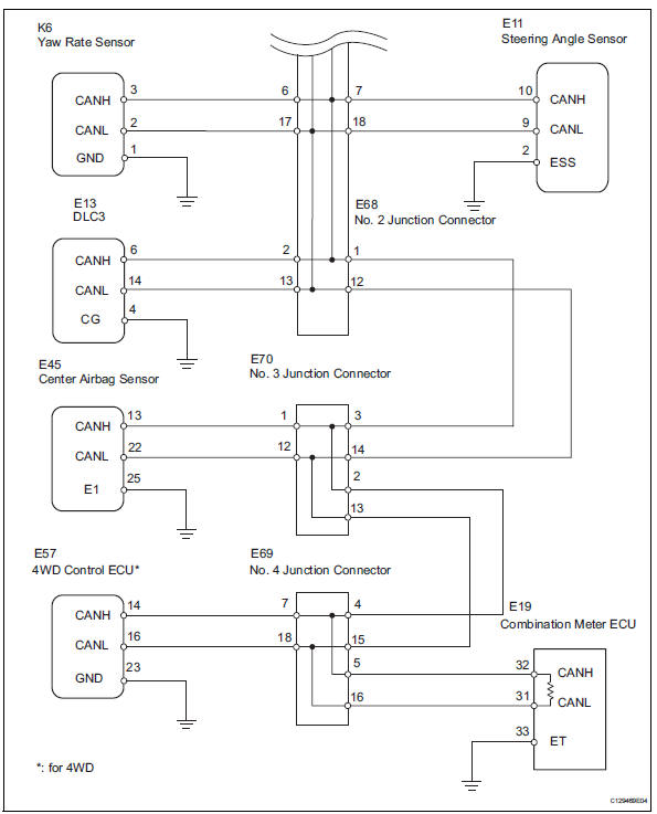
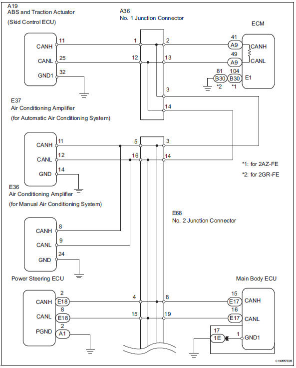
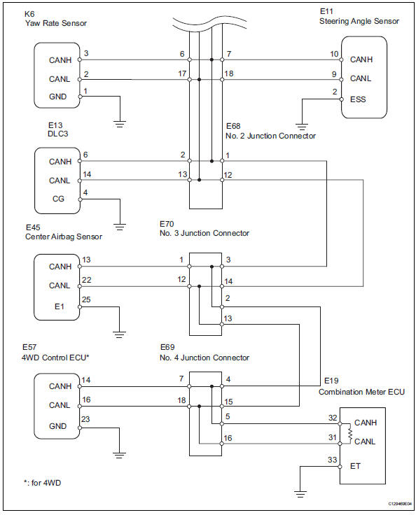
Wiring diagram
Inspection procedure
Notice:
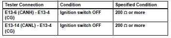
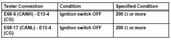
- Turn the ignition switch off before measuring the resistances of the main wire and the branch wire.
- After the ignition switch is turned off, check that the key reminder warning system and light reminder warning system are not in operation.
- Before measuring the resistance, leave the vehicle for at least 1 minute and do not operate the ignition switch, any switches or doors. If doors need to be opened in order to check connectors, open the doors and leave them open.
Hint:
Operating the ignition switch, any switches or any doors triggers related ecu and sensor communication with the can, which causes resistance variation.
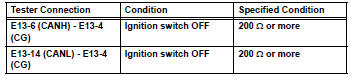
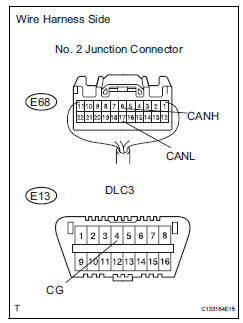
- Check can bus line for short to gnd (dlc3 branch wire)
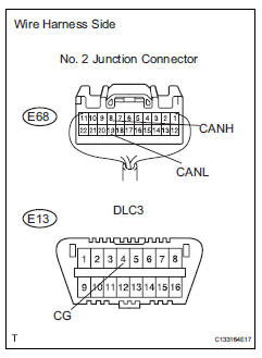
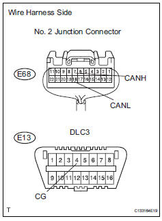
- Disconnect the e68 no. 2 Junction connector.
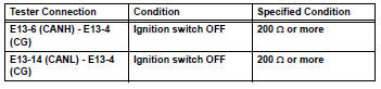
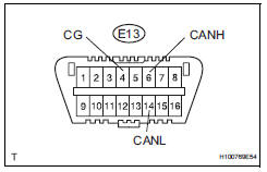
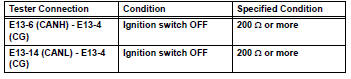
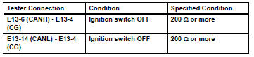
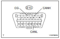
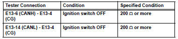
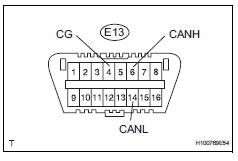
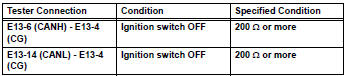
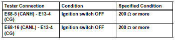
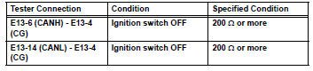
- Measure the resistance of the dlc3.
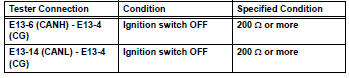
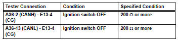
Standard resistance

- Connect connector
- Reconnect the e68 no. 2 Junction connector.

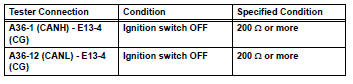
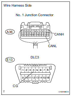
- Check can bus line for short to gnd (no. 1 Junction connector)
- Disconnect the a36 no. 1 Junction connector.
- Measure the resistance of the dlc3.
Standard resistance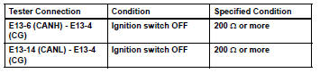

- Connect connector
- Reconnect the a36 no. 1 Junction connector.

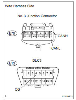
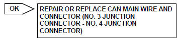
- Check can bus line for short to gnd (no. 3 Junction connector, no. 4 Junction connector side)
- Disconnect the e70 no. 3 Junction connector.
- Measure the resistance of the dlc3.
Standard resistance

- Connect connector
- Reconnect the e70 no. 3 Junction connector.

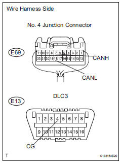
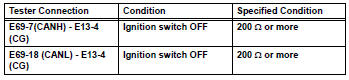
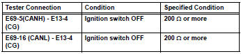
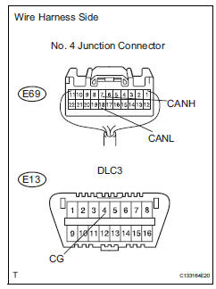
- Check can bus line for short to gnd (no. 4 Junction connector side)
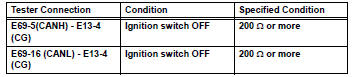
- Disconnect the e69 no. 4 Junction connector.
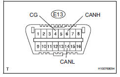
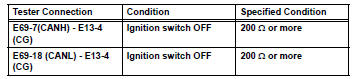
- Measure the resistance of the dlc3.
Standard resistance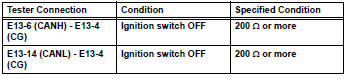

- Connect connector
- Reconnect the e69 no. 4 Junction connector.

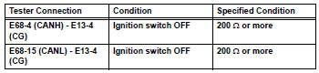
- Check can bus line for short to gnd (no. 3 Junction connector - center airbag sensor assembly)
- Disconnect the e70 no. 3 Junction connector.
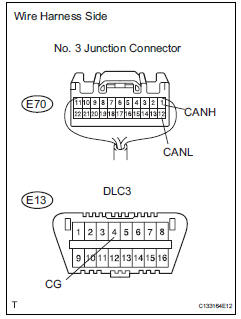
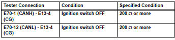
- Measure the resistance of the wire harness side connectors.
Standard resistance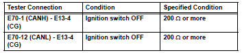

- Connect connector
- Reconnect the e70 no. 3 Junction connector.

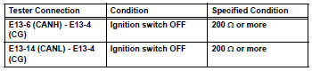
- Check can bus line for short to gnd (center airbag sensor assembly)
- Disconnect the e45 center airbag sensor connector.
- Measure the resistance of the dlc3.
Standard resistance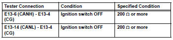

Replace center airbag sensor assembly
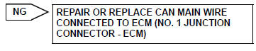
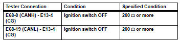
- Check can bus line for short to gnd (no. 1 Junction connector - ecm)
- Disconnect the a36 no. 1 Junction connector.
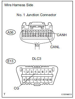
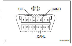
- Measure the resistance of the wire harness side connectors.
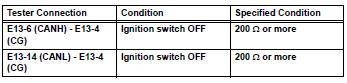
Standard resistance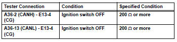


- Check can bus line for short to gnd (no. 1Junction connector - abs and traction actuator)
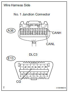
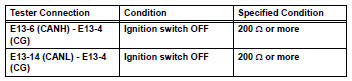
- Measure the resistance of the wire harness side connectors.
Standard resistance

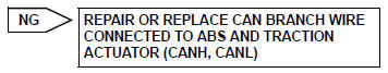
Repair or replace can main wire and connector (no. 1 Junction connector - no.
2 Junction connector)
- Connect connector
- Reconnect the a36 no. 1 Junction connector.

- Check can bus line for short to gnd (ecm)
- Disconnect the a9 ecm connector.
- Measure the resistance of the dlc3.
Standard resistance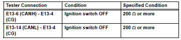

Replace ecm
- Connect connector
- Reconnect the a36 no. 1 Junction connector.

- Check can bus line for short to gnd (abs and traction actuator)
- Disconnect the a19 abs and traction actuator (skid control ecu) connector.
- Measure the resistance of the dlc3.
Standard resistance

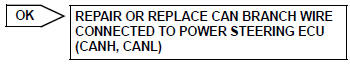
Replace power steering ecu
- Connect connector
- Reconnect the e68 no. 2 Junction connector.

- Check can bus line for short to gnd (main body ecu)
- Disconnect the e17 main body ecu connector.
- Measure the resistance of the dlc3.
Standard resistance

Replace instrument panel junction block (main body ecu)
- Connect connector
- Reconnect the e68 no. 2 Junction connector.

- Check can bus line for short to gnd (air conditioning amplifier)
- Disconnect the e37*1 or e36*2 air conditioning amplifier connector.
Hint:
- *1: For automatic air conditioning system.
- *2: For manual air conditioning system.
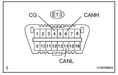
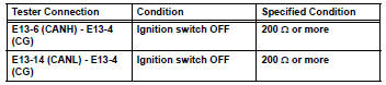
- Measure the resistance of the dlc3.
Standard resistance

Replace air conditioning amplifier
- Connect connector
- Reconnect the 68 no. 2 Junction connector.

- Check can bus line for short to gnd (steering angle sensor)
- Disconnect the e11 steering sensor connector.
- Measure the resistance of the dlc3.
Standard resistance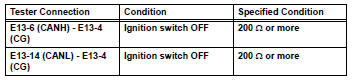

- Check can bus line for short to gnd (no. 4 Junction connector - 4wd control ecu)
Notice:
For vehicles without 4wd, go to "check can bus line for short to gnd (no. 4 Junction connector - combination meter ecu)".
- Measure the resistance of the wire harness side connectors.
Standard resistance


- Check can bus line for short to gnd (no. 4 Junction connector - combination meter ecu)
- Measure the resistance of the wire harness side connectors.
Standard resistance

- Connect connector
- Reconnect the e69 no. 4 Junction connector.

- Check can bus line for short to gnd (4wd control ecu)
- Disconnect the e57 4wd control ecu connector.
- Measure the resistance of the dlc3.
Standard resistance

Replace 4wd control ecu
- Connect connector
- Reconnect the e69 no. 4 Junction connector.

- Check can bus line for short to gnd (combination meter ecu)
- Disconnect the e19 combination meter ecu connector.
- Measure the resistance of the dlc3.
Standard resistance

Replace combination meter ecu
Short to gnd in can bus line (2006/01- )
Description
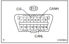
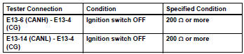
There may be a short circuit between the can bus line and gnd when there is resistance between terminals 6 (canh) and 4 (cg) or terminals 14 (canl) and 4 (cg) of the dlc3.
Wiring diagram
Inspection procedure
Notice:
- Turn the ignition switch off before measuring the resistances of the main wire and branch wire.
- After the ignition switch is turned off, check that the key reminder warning system and light reminder warning system are not in operation.
- Before measuring the resistance, leave the vehicle as is for at least 1 minute and do not operate the ignition switch, any other switches or the doors. If doors need to be opened in order to check connectors, open the doors and leave them open.
Hint:
Operating the ignition switch, any switches or any doors triggers related ecu and sensor communication with the can, which causes resistance variation.
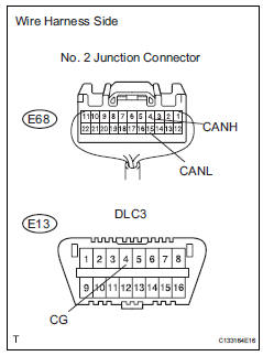
- Check can bus line for short to gnd (dlc3 branch wire)
- Disconnect the e68 no. 2 Junction connector.
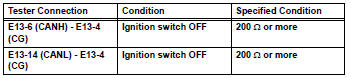
- Measure the resistance of the dlc3.
Standard resistance

- Connect connector
- Reconnect the e68 no. 2 Junction connector.

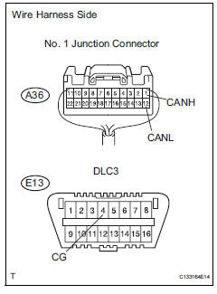
- Check can bus line for short to gnd (no. 1 Junction connector)
- Disconnect the a36 no. 1 Junction connector.
- Measure the resistance of the dlc3.
Standard resistance

- Connect connector
- Reconnect the a36 no. 1 Junction connector.

- Check can bus line for short to gnd (no. 3 Junction connector, no. 4 Junction connector side)
- Disconnect the e70 no. 3 Junction connector.
- Measure the resistance of the dlc3.
Standard resistance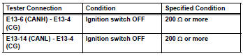

- Connect connector
- Reconnect the e70 no. 3 Junction connector.

- Check can bus line for short to gnd (no. 4 Junction connector side)
- Disconnect the e69 no. 4 Junction connector.
- Measure the resistance of the dlc3.
Standard resistance


- Connect connector
- Reconnect the e69 no. 4 Junction connector.

- Check can bus line for short to gnd (no. 3 Junction connector - center airbag sensor assembly)
- Disconnect the e70 no. 3 Junction connector.
- Measure the resistance of the wire harness side connectors.
Standard resistance

- Connect connector
- Reconnect the e70 no. 3 Junction connector.

- Check can bus line for short to gnd (center airbag sensor assembly)
- Disconnect the e45 center airbag sensor connector.
- Measure the resistance of the dlc3.
Standard resistance

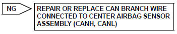
Replace center airbag sensor assembly
- Check can bus line for short to gnd (no. 1 Junction connector - ecm)
- Disconnect the a36 no. 1 Junction connector.
- Measure the resistance of the wire harness side connectors.
Standard resistance

- Check can bus line for short to gnd (no. 1 Junction connector - abs and traction actuator)
- Measure the resistance of the wire harness side connectors.
Standard resistance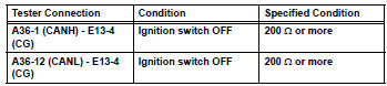

Repair or replace can main wire and connector (no. 1 Junction connector - no. 2 Junction connector)
- Connect connector
- Reconnect the a36 no. 1 Junction connector.

- Check can bus line for short to gnd (ecm)
- Disconnect the a9 ecm connector.
- Measure the resistance of the dlc3.
Standard resistance

Replace ecm
- Connect connector
- Reconnect the a36 no. 1 Junction connector.

- Check can bus line for short to gnd (abs and traction actuator)
- Disconnect the a19 abs and traction actuator (skid control ecu) connector.
- Measure the resistance of the dlc3.
Standard resistance

Replace abs and traction actuator (skid control ecu)
- Connect connector
- Reconnect the e70 no. 3 Junction connector.

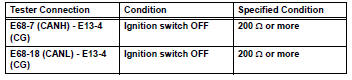
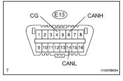
- Check can bus line for short to gnd (no. 2 Junction connector - yaw rate sensor)
- Disconnect the e68 no. 2 Junction connector.
- Measure the resistance of the wire harness side connectors.
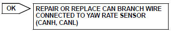
Standard resistance

- Check can bus line for short to gnd (no. 2 Junction connector - power steering ecu)
- Measure the resistance of the wire harness side connectors.
Standard resistance

- Check can bus line for short to gnd (no. 2 Junction connector - main body ecu)
- Measure the resistance of the wire harness side connectors.
Standard resistance

- Check can bus line for short to gnd (no. 2 Junction connector - air conditioning amplifier)

- Measure the resistance of the wire harness side connectors.
Standard resistance

- Check can bus line for short to gnd (no. 2 Junction connector - steering angle sensor)
- Measure the resistance of the wire harness side connectors.
Standard resistance

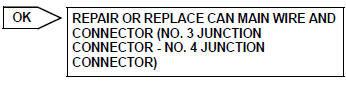
Repair or replace can main wire and connector (no. 2 Junction connector - no.
3 Junction connector)
- Connect connector
- Reconnect the e68 no. 2 Junction connector.

- Check can bus line for short to gnd (yaw rate sensor)
- Disconnect the k6 yaw rate sensor connector.
- Measure the resistance of the dlc3.
Standard resistance

replace yaw rate sensor
- Connect connector
- Reconnect the e68 no. 2 Junction connector.

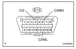
- Check can bus line for short to gnd (power steering ecu)
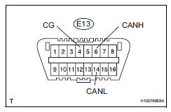
- Disconnect the e18 power steering ecu connector.
- Measure the resistance of the dlc3.
Standard resistance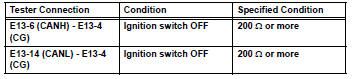

Replace power steering ecu
- Connect connector
- Reconnect the e68 no. 2 Junction connector.

- Check can bus line for short to gnd (main body ecu)
- Disconnect the e17 main body ecu connector.
- Measure the resistance of the dlc3.
Standard resistance

Replace instrument panel junction block (main body ecu)
- Connect connector
- Reconnect the e68 no. 2 Junction connector.

- Check can bus line for short to gnd (air conditioning amplifier)
- Disconnect the e37*1 or e36*2 air conditioning amplifier connector.
Hint:
*1: For automatic air conditioning system
*2: For manual air conditioning system
- Measure the resistance of the dlc3.
Standard resistance

Replace air conditioning amplifier
- Connect connector
- Reconnect the e68 no. 2 Junction connector.

- Check can bus line for short to gnd (steering angle sensor)
- Disconnect the e11 steering sensor connector.
- Measure the resistance of the dlc3.
Standard resistance

replace steering angle sensor
- Check can bus line for short to gnd (no. 4 Junction connector - 4wd control ecu)
Notice:
For vehicles without 4wd, go to "check can bus line for short to gnd (no. 4 Junction connector - combination meter ecu)".
- Measure the resistance of the wire harness side connectors.
Standard resistance

- Check can bus line for short to gnd (no. 4 Junction connector - combination meter ecu)
- Measure the resistance of the wire harness side connectors.
Standard resistance

Replace 4wd control ecu
- Connect connector
- Reconnect the e69 no. 4 Junction connector.

- Check can bus line for short to gnd (combination meter ecu)
- Disconnect the e19 combination meter ecu connector.
- Measure the resistance of the dlc3.
Standard resistance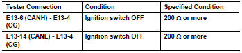

Replace combination meter ecu
 Short to b+ in can bus line
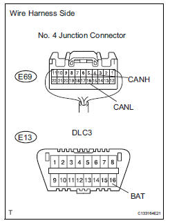
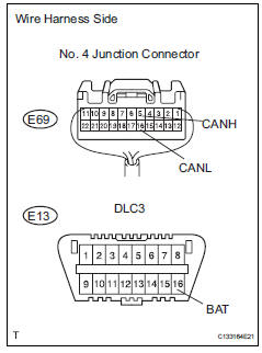
Description
There may be a short circuit between the can bus line and +b when there is
resistance between
terminals 6 (canh) and 16 (bat) or terminals 14 (canl) and 16 (bat) of the dlc3.
Wiri ...
 Open in one side of can branch line
Description
If 2 or more ecus and/or sensors do not appear on the intelligent tester's
"bus check" screen via the
can vim, one side of the can branch wire may be open. (One side of the c ...
Other materials:
Cleaning and protecting the vehicle exterior
Perform the following to
protect the vehicle and
maintain it in prime condition:
Cleaning instructions
Working from top to bottom,
liberally apply water to the
vehicle body, wheel wells and
underside of the vehicle to
remove any dirt and dust.
Wash the vehicle body using
a sponge or soft clo ...
Throttle actuator control throttle body range / performance
Description
The electronic throttle control system (etcs) is composed of the throttle
actuator, throttle position (tp)
sensor, accelerator pedal position (app) sensor, and ecm. The ecm operates the
throttle actuator to
regulate the throttle valve in response to driver inputs. The tp senso ...
Reassembly
Hint:
When installing the ornament plate and emblem, heat the
radiator grille, ornament plate and emblem using a heat light.
Standard heating temperature
Notice:
Do not heat the emblem base and emblem excessively.
Install radiator grille emblem
Attach the 4 claws to install the radi ...
