Toyota RAV4 (XA40) 2013-2018 Service Manual: Center airbag sensor assembly communication circuit malfunction

Description
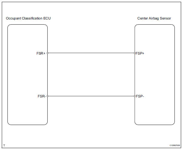
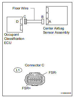
The center airbag sensor communication circuit consists of the occupant classification ecu and the center airbag sensor.
Dtc b1790 is recorded when a malfunction is detected in the center airbag sensor communication circuit.
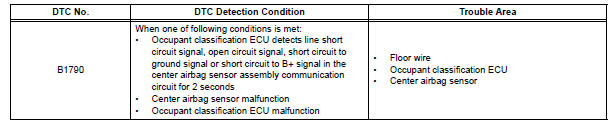
Wiring diagram
Inspection procedure
Hint:
- If troubleshooting (wire harness inspection) is difficult to perform, remove the front passenger seat installation bolts to see the undersurface of the seat cushion.
- In the above case, hold the seat so that it does not tip over. Holding the seat for a long period of time may cause a problem, such as seat rail deformation. Hold the seat up only for as long as necessary.
- Check for dtc
- Turn the ignition switch on.
- Clear the dtcs (see page rs-249).
Hint:
First clear dtcs stored in the occupant classification ecu and then in the center airbag sensor.
- Turn the ignition switch off.
- Turn the ignition switch on.
- Check the dtcs (see page rs-249).
Ok: dtc b1790 is not output.
Hint:
Dtcs other than dtc b1790 may be output at this time, but they are not related to this check.

- Check connection of connector
- Turn the ignition switch off.
- Disconnect the cable from the negative (-) battery terminal, and wait for at least 90 seconds.
- Check that the connectors are properly connected to the occupant classification ecu and the center airbag sensor.
Ok: the connectors are properly connected.

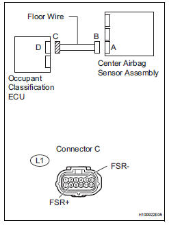
- Check floor wire (to b+)
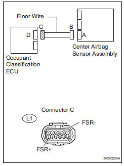
- Disconnect the connectors from the occupant classification ecu and the center airbag sensor.
- Connect the cable to the negative (-) battery terminal, and wait for at least 2 seconds.
- Turn the ignition switch on.
- Measure the voltage of the wire harness side connector.
Standard voltage 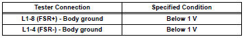

- Check floor wire (for open)
- Turn the ignition switch off.
- Disconnect the cable from the negative (-) battery terminal, and wait for at least 90 seconds.
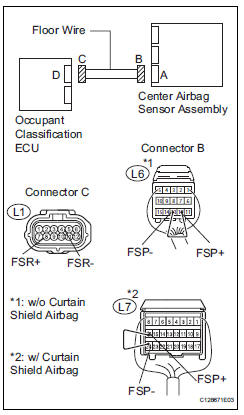
- Using a service wire, connect terminals l6-12 (fsp+) *1 and l6-13 (fsp-) *1 or l7-16 (fsp+) *2 and l7-24 (fsp-) *2 of connector b.
Notice:
Do not forcibly insert a service wire into the terminals of the connector when connecting them.
- Measure the resistance of the wire harness side connector.
Standard resistance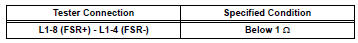
Hint:
*1: W/o curtain shield airbag
*2: W/ curtain shield airbag


- Check floor wire (for short)
- Disconnect the service wire from connector b.
- Measure the resistance of the wire harness side connector.
Standard resistance 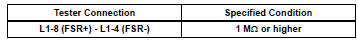

- Check floor wire (to ground)
- Measure the resistance of the wire harness side connector.
Standard resistance 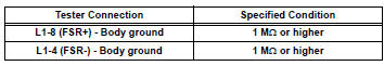

- Check for dtc
- Connect the connectors to the occupant classification ecu and the center airbag sensor.
- Connect the cable to the negative (-) battery terminal, and wait for at least 2 seconds.
- Turn the ignition switch on.
- Clear the dtcs (see page rs-249).
Hint
First clear dtcs stored in the occupant classification ecu and then in the center airbag sensor.
- Turn the ignition switch off.
- Turn the ignition switch on.
- Check the dtcs (see page rs-249).
Ok: dtc b1790 is not output.
Hint:
Dtcs other than dtc b1790 may be output at this time, but they are not related to this check.

- Replace occupant classification ecu
- Turn the ignition switch off.
- Disconnect the cable from the negative (-) battery terminal, and wait for at least 90 seconds.
- Replace the occupant classification ecu (see page rs- 392).
Hint:
Perform the inspection using parts from a normal vehicle if possible.

- Perform zero point calibration
- Connect the cable to the negative (-) battery terminal, and wait for at least 2 seconds.
- Connect the intelligent tester (with can vim) to the dlc3.
- Turn the ignition switch on.
- Using the intelligent tester, perform the zero point calibration (see page rs-241).
Ok: completed is displayed.

- Perform sensitivity check
- Using the intelligent tester, perform the sensitivity check (see page rs-241).
Standard value: 27 to 33 kg (59.52 To 72.75 Lb)

- Check for dtc
- Turn the ignition switch on.
- Clear the dtcs (see page rs-249).
Hint:
First clear dtcs stored in the occupant classification ecu and then in the center airbag sensor.
- Turn the ignition switch off.
- Turn the ignition switch on.
- Check the dtcs (see page rs-249).
Ok: dtc b1790 is not output.
Hint:
Dtcs other than dtc b1790 may be output at this time, but they are not related to this check.

End
 Rear occupant classification sensor rh collision detection
Description
Dtc b1788 is output when the occupant classification ecu receives a collision
detection signal sent by
the rear occupant classification sensor rh when an accident occurs.
Dtc b1 ...
 Occupant classification sensor power supply circuit malfunction
Description
The occupant classification sensor power supply circuit consists of the
occupant classification ecu and
the occupant classification sensors.
Dtc b1793 is recorded when a malfunc ...
Other materials:
Only rear door lh lock / unlock functions do not operate
Description
The main body ecu receives lock / unlock switch signals and activates the
door lock motor accordingly.
Wiring diagram
Inspection procedure
Inspect rear door with motor lock assembly lh
Apply the battery voltage to the door lock motor and
check the operation of th ...
Inside rear view mirror
The rear view mirror’s position can be adjusted to enable sufficient
confirmation of the rear view.
Adjusting the height of rear view mirror
The height of the rear view mirror can be adjusted to suit your driving
posture.
Adjust the height of the rear view
mirror by moving it up and down.
...
Problem symptoms table
Hint:
Use the table below to help determine the cause of the
problem symptom. The potential causes of the symptoms
are listed in order of probability in the "suspected area"
column of the table. Check each symptom by checking the
suspected areas in the order they are listed. Re ...
