Toyota RAV4 (XA40) 2013-2018 Service Manual: Mass air flow circuit range / performance problem
Description
Refer to dtc p0100 (see page es-86).
Monitor description
The maf meter is a sensor that measures the amount of air flowing through the throttle valve. The ecm uses this information to determine the fuel injection time and to provide an appropriate air-fuel ratio. Inside the maf meter, there is a heated platinum wire which is exposed to the flow of intake air. By applying a specific electrical current to the wire, the ecm heats it to a specific temperature. The flow of incoming air cools both the wire and an internal thermistor, affecting their resistance. To maintain a constant current value, the ecm varies the voltage applied to these components of the maf meter. The voltage level is proportional to the airflow through the sensor, and the ecm uses it to calculate the intake air volume.
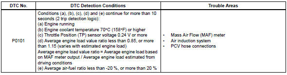
The ecm monitors the average engine load value ratio to check the maf meter for malfunctions. The average engine load value ratio is obtained by comparing the average engine load calculated from the maf meter output to the average engine load estimated from the driving conditions, such as the engine speed and the throttle opening angle. If the average engine load value ratio is below the threshold value, the ecm determines that the intake air volume is low, and if the average engine load value ratio is above the threshold value, the ecm determines that the intake air volume is high.
If this is detected in 2 consecutive driving cycles, the mil is illuminated and a dtc is set.
Monitor strategy
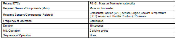
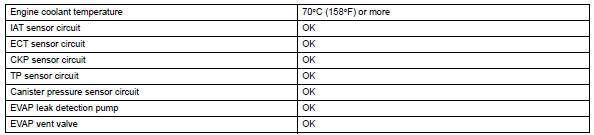
Typical enabling conditions
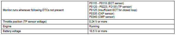
Typical malfunction thresholds

Wiring diagram
Refer to dtc p0100 (see page es-88).
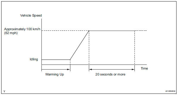
Confirmation driving pattern
Hint:
Performing this confirmation pattern will activate the mass air flow performance monitor.
- Connect the intelligent tester to the dlc3.
- Turn the ignition switch on.
- Turn the tester on.
- Clear dtcs (see page es-35).
- Start the engine, and warm it up until the engine coolant temperature reaches 70°c (158°f) or higher.
- Drive the vehicle at approximately 100 km/h (62 mph) for 20 seconds or more.
- On the tester, select the following menu items: diagnosis / enhanced obd ii / dtc info / pending codes and check if any dtcs (any pending dtcs) are set.
Inspection procedure
Hint:
Read freeze frame data using the intelligent tester. Freeze frame data records the engine condition when malfunctions are detected. When troubleshooting, freeze frame data can help determine if the vehicle was moving or stationary, if the engine was warmed up or not, if the air-fuel ratio was lean or rich, and other data from the time the malfunction occurred.
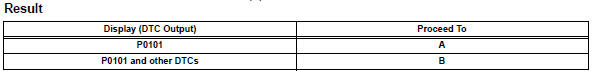
- Check any other dtcs output (in addition to dtc p0101)
- Connect the intelligent tester to the dlc3.
- Turn the ignition switch on.
- Turn the tester on.
- Select the following menu items: diagnosis / enhanced obd ii / dtc info / current codes.
- Read dtcs.
Hint:
If any dtcs other than p0101 are output, troubleshoot those
dtcs first. 

- Check air induction system
- Check the air induction system for vacuum leakage.
Ok:
No leakage from air induction system.

- Check pcv hose connections
Ok:
Pcv hose is connected correctly and is not damaged.


Replace mass air flow meter
 Mass or volume air flow circuit
Description
The mass air flow (maf) meter is a sensor that measures the amount of air
flowing through the throttle
valve.
The ecm uses this information to determine the fuel injection time ...
 Intake air temperature circuit malfunction
Description
The intake air temperature (iat) sensor, mounted on the mass air flow (maf)
meter, monitors the iat.
The iat sensor has a built-in thermistor with a resistance that varies ac ...
Other materials:
Light control switch circuit
Description
This circuit detects the state of the headlight dimmer switch.
Wiring diagram
Inspection procedure
Read value of intelligent tester (main body ecu)
Connect the intelligent tester to the dlc3.
Turn the ignition switch on and press the intelligent
tester main switch on ...
Installation with latch system
Adjust the seatback to the 8th
lock position from the fully
reclined position.
Fully reclined position
8Th lock position
If your child restraint system interferes with a head restraint and
cannot be installed properly, install the child restraint system after
removing the hea ...
Tire inflation pressure
Tire inflation pressure
The recommended cold tire inflation
pressure and tire size are displayed
on the tire and loading
information label.
Inspection and adjustment procedure
Tire valve
Tire pressure gauge
Remove the tire valve cap.
Press the tip of the tire pressure gaug ...
