
Toyota RAV4 (XA40) 2013-2018 Service Manual: Receiver error

Description

Wiring diagram
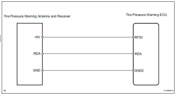
Inspection procedure
Notice:
It is necessary to register an id code after replacing the tire pressure warning valve abd transmitter and/or the tire pressure warning ecu (see page tw-9).
Hint:
Set the tire pressure to the specified value.
Standard pressure: 220 kpa (2.2 Kgf/cm2, 32 psi)
- Check tire pressure warning ecu
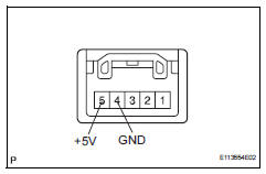
- Measure the voltage of the connector.
Standard voltage 


- Check wire harness (ecu - receiver)
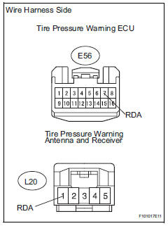
- Disconnect the e56 ecu connector.
- Disconnect the l20 receiver connector.
- Measure the resistance of the wire harness side connectors.
Standard resistance 


- Replace tire pressure warning antenna and receiver

- Check dtc
- Check for dtc (see page tw-20).
Ok: dtc is not output.
Hint:
- It is necessary to register an id when replacing the tire pressure warning ecu (see page tw-9).
- Read id on the data list before removing the tire pressure warning ecu. Register the id in the new tire pressure warning ecu.


End
- Check wire harness (ecu - receiver)
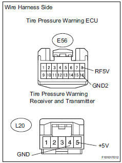
- Disconnect the e56 ecu connector.
- Disconnect the l22 receiver connector.
- Measure the resistance of the wire harness side connectors.
Standard resistance 


Replace tire pressure warning ecu
 Transmitter id not registered in main mode
Description
Inspection procedure
Notice:
It is necessary to register an id code after replacing the tire pressure
warning valve and
transmitter and/or the tire pressure monitor ecu (see ...
 Vehicle speed signal error (test mode dtc)
Description
The tire pressure warning ecu receives a speed signal from the combination
meter. This dtc is stored
upon entering test mode, and cleared when a vehicle speed signal of 12 mph (20 ...
Other materials:
Turn signal light circuit
Description
The turn signal flasher relay (marking: flsh) in the main body ecu turns on
when it receives signals
from the headlight dimmer switch integrated with the turn signal switch, causing
the turn signal lights to
flash.
Wiring diagram
Inspection procedure
Check operation of t ...
Operating instructions
Turning the end of the lever turns on the lights as follows:
Type a
The side marker, parking,
tail, license plate, daytime
running lights and instrument
panel lights turn on.
The headlights and all
lights listed above (except
daytime running lights)
turn on.
The headlights an ...
Low pitched horn
Components
Removal
Remove radiator support opening cover
(see page et-4)
Remove front fender liner lh (see page et-4)
Remove front fender liner rh (see page et-4)
Remove front bumper cover (see page et-5)
Remove low pitched horn
Disconnect the horn connector.
Remove th ...
