
Toyota RAV4 (XA40) 2013-2018 Service Manual: Terminals of ecu
- Check combination meter assembly
- Disconnect the e19 meter connector.
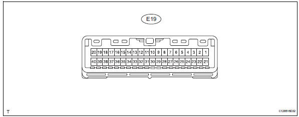
- Measure the voltage and resistance of the wire harness side connector.
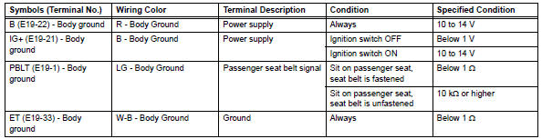
If the result is not as specified, there may be a malfunction on the wire harness side.
- Check heater control panel (for automatic air conditioning system)
- Disconnect the e23 panel connector.

- Measure the voltage and resistance of the wire harness side connector.
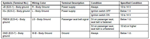
If the result is not as specified, there may be a malfunction on the wire harness side.
- Check clock assembly (for manual air conditioning system)

- Disconnect the e22 clock connector.
- Measure the voltage and resistance of the wire harness side connector.
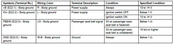
If the result is not as specified, there may be a malfunction on the wire harness side.
 Problem symptoms table
Hint:
Use the table below to help determine the cause of the
problem symptom. The potential causes of the symptoms are
listed in order of probability in the "suspected area" column
of th ...
 Diagnosis system
Description
Data of the system can be read through the data
link connector 3 (dlc3) of the vehicle.
Therefore, when the system seems to be
malfunctioning, use the intelligent tester t ...
Other materials:
Indications on multi-information
display
Vehicles with 7-inch display
LTA indicator
The illumination condition of the
indicator informs the driver of the
system operation status.
Illuminated in white: LTA system is
operating.
Illuminated in green: Steering
wheel assistance of the steering
assist function or lane centering
function is ...
Panoramic moon roof
Use the overhead switches
to operate the panoramic
moon roof and electronic
sunshade.
Operating the electronic
sunshade and panoramic
moon roof
â– Opening and closing the
electronic sunshade
Opens the electronic sunshade*
Slide and hold the switch
backward. The electronic sunshade
will fully ...
Vehicle lift and support locations
Notice about vehicle condition when
jacking up vehicle
The vehicle must be unloaded before jacking up /
lifting up the vehicle. Never jack up / lift up a heavily
loaded vehicle.
When removing heavy parts such as the engine and
transmission, the center of gravity of the vehicle
m ...
