Toyota RAV4 (XA40) 2013-2018 Service Manual: Air conditioning control panel does not operate
Description
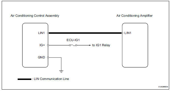
This circuit consists of the air conditioning control and the air conditioning amplifier. When the air conditioning control is operated, signals are transmitted to the air conditioning amplifier through the lin communication system.
If the lin communication system malfunctions, the air conditioning amplifier does not operate even if the air conditioning control is operated.
Wiring diagram
Inspection procedure
- Check wire harness (air conditioning control assembly - body ground)
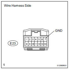
- Disconnect the air conditioning control assembly connector.
- measure the resistance of the wire harness side connector.
Standard resistance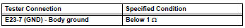

- Check wire harness (air conditioning control assembly - battery)
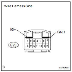
- Disconnect the e23 air conditioning control assembly connector.
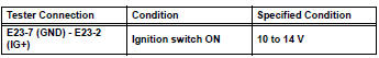
- Measure the voltage of the wire harness side connector.
Standard voltage

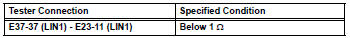
- Check wire harness (air conditioning amplifier - air conditioning control)
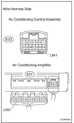
- Disconnect the e23 control connector.
- Disconnect the e37 amplifier connector.
- Measure the resistance of the wire harness side connectors.
Standard resistance

- Replace air conditioning amplifier
- Replace the air conditioning control with a new or properly functioning one.
- Operate the air conditioning control to check that it functions properly.
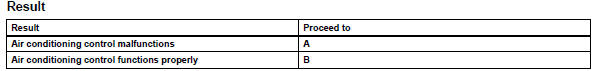

Replace air conditioning amplifier
 Multiplex communication circuit
Description
The air conditioning amplifier communicates data with the ecm and combination
meter through the can
communication system.
Wiring diagram
Inspection procedure
Check dt ...
 Blower motor circuit
Description
The blower motor is operated by signals from the air conditioning amplifier.
Blower motor speed signals
are transmitted in accordance with changes in the duty ratio.
Wiring diagra ...
Other materials:
On-vehicle inspection
Check driver side seat belt warning light
Turn the ignition switch on.
When the driver side seat belt is not fastened, check
that the combination meter's driver side seat belt
warning light starts blinking.
When the seat belt is fastened, check that the
combination meter's driver ...
Installation
Replace roof carrier seal
Remove the seals.
Install new seals as shown in the illustration.
Install roof rack leg front lh
Install the leg cushion front.
Install the roof rack leg front with the 2 screws.
Torque: 2.8 To 5.0 N*m (29 to 51 kgf*cm, 25 to 44
in.*Lbf)
...
If you think
something is wrong
If you notice any of the following symptoms, your vehicle probably
needs adjustment or repair. Contact your toyota dealer as
soon as possible.
Visible symptoms
Fluid leaks under the vehicle
(water dripping from the air conditioning after use is normal.)
Flat-looking tires or uneven tire w ...
