Toyota RAV4 (XA40) 2013-2018 Service Manual: Air-fuel ratio (a/f) and heated oxygen (ho2) sensor monitors (active air-fuel ratio control type)

- Preconditions
The monitor will not run unless:
- 2 Minutes or more have elapsed since the engine was started.
- The engine coolant temperature (ect) is 75°c (167°f) or more.
- Cumulative driving time at a vehicle speed of 48 km/h (30 mph) or more exceeds 6 minutes.
- Air-fuel ratio feedback control is performed.
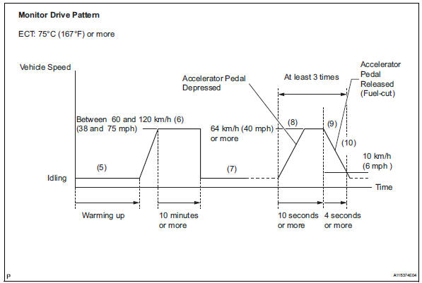
- Drive pattern for front a/f sensor and ho2 sensor
- Connect the intelligent tester to the dlc3.
- Turn the ignition switch on.
- Turn the tester on.
- Clear dtcs (see page es-35).
- Start the engine, and warm it up until the ect reaches 75°c (167°f) or higher.
- Drive the vehicle at between 60 km/h (38 mph) and 120 km/h (75 mph) for at least 10 minutes.
- Change the transmission to 2nd gear.
- Accelerate the vehicle to 64 km/h (40 mph) or more by depressing the accelerator pedal for at least 10 seconds.
- Soon after performing step (8) above, release the accelerator pedal for at least 4 seconds without depressing the brake pedal, in order to execute fuelcut control.
- Allow the vehicle to decelerate until the vehicle speed declines to less than 10 km/h (6 mph).
- Repeat steps from (8) through (10) above at least 3 times in one driving cycle.
- Monitor status
- Check the readiness monitor status displayed on the tester.
- If the status does not switch to compl (complete), make sure that the preconditions have been met, and then perform steps from (5) through (11) in the drive pattern above.
 Catalyst monitor (active air-fuel ratio control type)
Preconditions
The monitor will not run unless:
The mil is off.
Drive pattern
Connect the intelligent tester to the dlc3.
Turn the ignition switch on.
Turn the tester on.
...
 Air-fuel ratio (a/f) and heated oxygen (ho2) sensor
heater monitors (front a/f and rear ho2 sensor type)
Preconditions
The monitor will not run unless:
The mil is off.
Drive pattern
Connect the intelligent tester to the dlc3.
Turn the ignition switch on.
Turn the tester on.
...
Other materials:
Front passenger occupant classification system
Your vehicle is equipped with a front passenger occupant classification
system. This system detects the conditions of the front
passenger seat and activates or deactivates the devices for the
front passenger.
Seat belt reminder light
Srs warning light
“Air bag off” indicator light ...
Dtc check / clear
Notice:
When the diagnosis system is changed from normal
mode to check mode or vice versa, all dtcs and freeze
frame data recorded in normal mode are erased. Before
changing modes, always check and make a note of any
dtcs and freeze frame data.
Hint:
Dtcs which are stored in the ecm can be ...
Data list / active test (2006/01- )
Read data list
Hint:
Using the intelligent tester's data list allows switch,
sensor, actuator and other item values to be read without
removing any parts. Reading the data list early in
troubleshooting is one way to save time.
Connect the intelligent tester (with can vim) to the
...
