Toyota RAV4 (XA40) 2013-2018 Service Manual: Blower unit
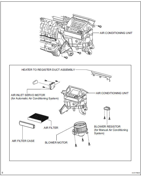
Components
Removal
- Disconnect cable from negative battery terminal
Caution:
Wait at least 90 seconds after disconnecting the cable from the negative (-) battery terminal to prevent airbag and seat belt pretensioner activation.
- Remove upper instrument panel
- Remove the upper instrument panel (see page ip- 4).
- Remove lower instrument panel
- Remove the lower instrument panel (see page ip- 16).
- Remove air duct (see page ac-188)
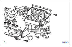
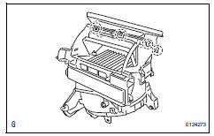
- Remove air conditioning unit
- Remove the air conditioning unit (see page ac- 185).
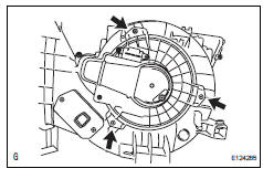
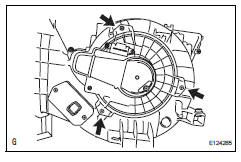
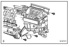
- Remove blower assembly
- Remove the 3 screws and blower.
Disassembly
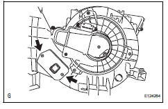
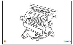
- Remove heater to register duct assembly
- Detach the 7 claws and register duct.
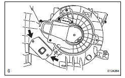
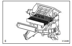
- Remove air filter case
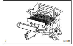
- Detach the 2 claws and remove the air filter case.
- Remove the air filter.
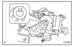
- Remove air inlet control servo motor (for manual air conditioning system)
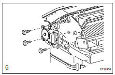
- Remove the 3 screws and air inlet servo motor.
- Remove air inlet control servo motor (for automatic air conditioning system)
- Detach the claws and lever.
- Remove the 3 screws and air inlet servo motor.
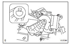
- Remove blower resistor (for manual air conditioning system)
- Remove the 2 screws and blower resistor.
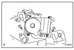
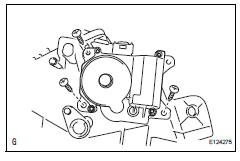
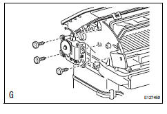
- Remove blower motor
- Remove the 3 screws and blower motor.
Reassembly
- Install blower motor
- Install the blower motor with the 3 screws.
- Install blower resistor (for manual air conditioning system)
- Install the blower resistor with the 2 screws.
- Install air inlet control servo motor (for automatic air conditioning system)
- Install the air inlet servo motor with the 3 screws.
- Attach the claw to install the lever.
- Install air inlet control servo motor (for manual air conditioning system)
- Install the air inlet servo motor with the 3 screws.
- Install air filter case
- Install the air filter.
- Attach the 2 claws to install the air filter case.
- Install heater to register duct assembly
- Attach the 7 claws to install the register duct.
Installation
- Install blower assembly
- Install the blower assembly with the 3 screws.
- Install air conditioning unit
- Install the air conditioning unit (see page ac-197).
- Install air duct (see page ac-199)
- Install lower instrument panel
- Install the lower instrument panel (see page ip-23).
- Install upper instrument panel
- Install the upper instrument panel (see page ip-9).
- Connect cable to negative battery terminal
- Check srs warning light
- Check the srs warning light (see page rs-37).
 Installation
Install air conditioner unit assembly
Install the a/c unit with the bolt and nut.
Torque: 9.8 N*m (100 kgf*cm, 7 ft.*Lbf)
Install instrument panel reinforcement
Install th ...
 Blower motor
On-vehicle inspection
Inspect blower motor (for automatic air conditioning system)
Disconnect the blower motor connector.
Connect the positive (+) lead from the battery to
terminal 1 ...
Other materials:
Steering wheel audio switches
Some audio features can be controlled using the switches on
the steering wheel.
Operation may differ depending on the type of audio system or
navigation system. For details, refer to the manual provided with
the audio system or navigation system.
Operating the audio system using the steering ...
Reassembly
Install generator rotor assembly
Install the washer onto the generator rectifier end
frame.
Install the generator rotor onto the generator
rectifier end frame.
Using a 32 mm socket wrench and press, slowly
push the generator drive end frame onto the
generator ...
Fuel system
Precaution
Before working on fuel system
Do not work near an open flame.
Keep gasoline away from rubber and leather parts.
Discharge the fuel pressure before disconnecting
the fuel line to prevent gasoline from spilling out.
Refer to the following procedure.
Discharge fuel ...
