Toyota RAV4 (XA40) 2013-2018 Service Manual: Installation
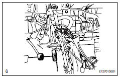
- Install air conditioner unit assembly
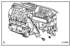
- Install the a/c unit with the bolt and nut.
Torque: 9.8 N*m (100 kgf*cm, 7 ft.*Lbf)
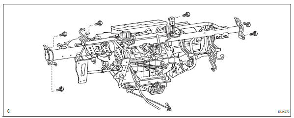
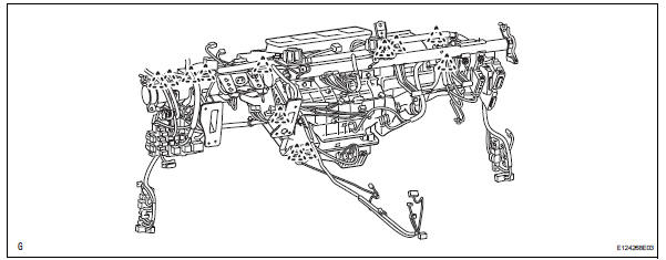
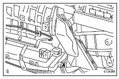
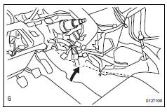
- Install instrument panel reinforcement
- Install the instrument panel reinforcement with the 6
bolts.
Torque: 20 n*m (204 kgf*cm, 15 ft.*Lbf)
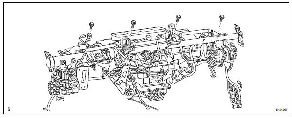
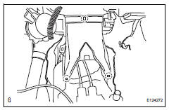
- Install the 3 bolts.
Torque: 9.8 N*m (100 kgf*cm, 7 ft.*Lbf)
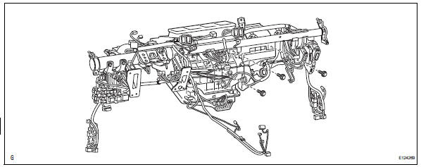
- Install the 4 bolts and connect the ground wire.
- Attach the 12 clamps.
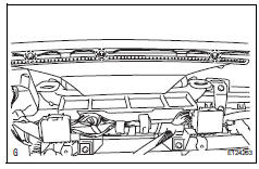
- Install drain cooler hose
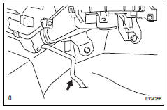
- Install the drain hose.
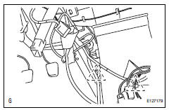
- Install air conditioning amplifier assembly
- Install the a/c amplifier with the screw.
- Connect the connector.
- Attach the 2 clamps to the amplifier.
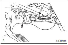
- Install air duct
- Attach the 2 claws and install the air duct.
- Install rear air duct
- Attach the 3 claws and install the air duct rear.
- Attach the 2 clamps and install the wire harness.
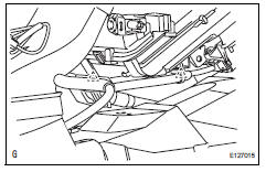
- Install no. 1 Instrument panel brace subassembly
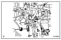
- Install the instrument panel brace with the bolt, nut and screw.
- Install the clamp and connect the wire harness.
- Reposition the floor carpet.
- Install defroster nozzle assembly
- Attach the 3 claws and install the defroster nozzle assembly lower.
- Install lower instrument panel
- Install the lower instrument panel (see page ip-23).
- Install upper instrument panel
- Install the upper instrument panel (see page ip-9).
- Install steering column assembly
- Install the steering column (see page sr-19).
- Connect heater water outlet hose
- Connect the water hose and attach the clip.
- Connect heater water inlet hose
Hint:
Use the same procedures described for the water outlet hose.
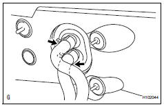
- Connect tube sub-assembly
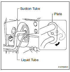
- Remove the attached vinyl tape from the pipe.
- Sufficiently apply compressor oil to new 2 o-rings and the fitting surface of the suction tube and liquid tube.
Compressor oil: nd-oil 8 or equivalent
- Install the 2 o-rings on the suction tube and liquid tube.
- Connect the suction tube and liquid tube.
Hint:
After the connection, check that the claw of the piping clamp is engaged.
- Install the plate with the bolt.
Torque: 9.8 N*m (100 kgf*cm, 7 ft.*Lbf)
- Connect cable to negative battery terminal
- Check srs warning light
- Check the srs warning light (see page rs-37).
- Replace engine coolant refer to the following procedures (see page co-6).
- Charge refrigerant (see page ac-172)
- Warm up engine (see page ac-173)
- Check for engine coolant leaks
- Check for leakage of refrigerant (see page ac-173)
 Reassembly
Install evaporator temperature sensor
Notice:
If reusing the evaporator, do not insert the sensor to
a location where the sensor was previously inserted.
Insert the sensor within range c sh ...
 Blower unit
Components
Removal
Disconnect cable from negative battery
terminal
Caution:
Wait at least 90 seconds after disconnecting the
cable from the negative (-) battery terminal to
prevent ai ...
Other materials:
Deterioration of battery
Description
The ecm determines the battery power according to the voltage of the batt
terminal while the engine is
running (not cranking).
Inspection procedure
Inspect battery
Inspect the battery specific gravity.
Check the specific gravity of each cell.
Standard gravity: ...
Components
(2005/11-2006/01)
...
System description
General
In conjunction with an impact absorbing structure for
a frontal collision, the srs (supplemental restraint
system) driver airbag, front passenger airbag and
driver side knee airbag were designed to
supplement seat belts in the event of a frontal
collision in order to help ...
