Toyota RAV4 (XA40) 2013-2018 Service Manual: Reassembly
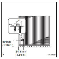
- Install evaporator temperature sensor
Notice:
If reusing the evaporator, do not insert the sensor to a location where the sensor was previously inserted.
Insert the sensor within range c shown in the illustration.
- Install the evaporator temperature sensor as shown in the illustration.
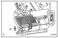
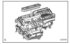
- Install no. 1 Cooler evaporator subassembly
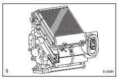
- Install the cooler thermistor and cooler evaporator on the case.
- Attach the temperature sensor clamp.
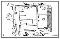
- Attach the 2 claws to install the cover.
- Install the 4 screws.
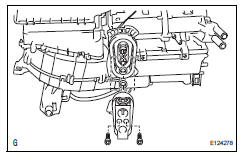
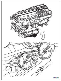
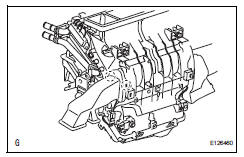
- Install cooler expansion valve
- Sufficiently apply compressor oil to 2 new o-rings and the fitting surface of the hose joint.
Compressor oil: nd-oil 8 or equivalent
- Install the 2 o-rings to the cooler evaporator.
- Install the cooler expansion valve.
- Using a 4 mm hexagon wrench, install the a/c tube with the 2 hexagon bolts.
Torque: 3.5 N*m (35 kgf*cm, 30 in.*Lbf)
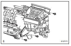
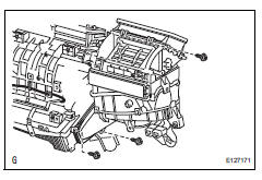
- Install heater radiator unit sub-assembly
- Install the heater radiator with the clamp and screw.
- Install airmix damper control cable subassembly (for manual air conditioning system)
- Attach the 3 claws to install the cable.
- Install mode control cable assembly (for manual air conditioning system)

- Attach the 3 claws to install the cable.
- Attach the evaporator case to the blower case.
- Install the cable with the 3 screws.
- Install air mix control servo motor
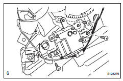
- Install the air mix control servo motor with the 3 screws and connect the connector.
- Install air outlet control servo motor
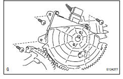
- Install the air outlet control servo motor with the 3 screws and connect the connector.
- Attach the evaporator case to the blower case.
- Install the 3 screws.
- Install air duct
- Attach the 2 claws and install the air duct.
- Install no. 3 Heater to register duct
- Attach the 6 claws and install the heater to register duct.
 Disassembly
Remove no. 3 Heater to register duct
Detach the 6 claws and remove the heater to
register duct.
Remove air duct
Detach the 2 claws and remove the air duct.
Remove ...
 Installation
Install air conditioner unit assembly
Install the a/c unit with the bolt and nut.
Torque: 9.8 N*m (100 kgf*cm, 7 ft.*Lbf)
Install instrument panel reinforcement
Install th ...
Other materials:
Floor shift assembly
Components
Removal
Disconnect cable from negative battery
terminal
Caution:
Wait at least 90 seconds after disconnecting the
cable from the negative (-) battery terminal to
prevent airbag and seat belt pretensioner activation.
Remove shift lever knob sub-assembly
Remove re ...
Receiving a call
When a call is received, the following screen is displayed
together with a sound.
To answer the phone
Press the switch on the
steering
wheel or select .
To refuse a call
Press the switch on the
steering wheel or select .
To adjust the incoming call volume
...
Open in can main wire
Description
There may be an open circuit in the can main wire and / or the dlc3 branch
wire when the resistance
between terminals 6 (canh) and 14 (canl) of the dlc3 is 69 ù or more.
Wiring diagram
Inspection procedure
Notice:
Turn the ignition switch off before measuring th ...
