Toyota RAV4 (XA40) 2013-2018 Service Manual: Center airbag sensor assembly malfunction
![]()
Description
The center airbag sensor consists of the airbag sensor, the safing sensor, the drive circuit, the diagnosis circuit and the ignition control.
If the center airbag sensor receives signals from the airbag sensor, it determines whether or not the srs should be activated.
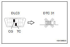
Dtc b1000/31 is recorded when a malfunction is detected in the center airbag sensor.
![]()
Hint:
When a malfunction code is displayed simultaneously with dtc b1000/31, repair the malfunction indicated by this code (except dtc b1000/31) first.
Inspection procedure
- Check center airbag sensor assembly
- Turn the ignition switch off.
- Disconnect the cable from the negative (-) battery terminal, and wait for at least 90 seconds.
- Connect the cable to the negative (-) battery terminal, and wait for at least 2 seconds
- Turn the ignition switch on, and wait for at least 60 seconds.
- Clear the dtcs (see page rs-49).
- Turn the ignition switch off.
- Turn the ignition switch on, and wait for at least 60 seconds.
- Check the dtcs (see page rs-49).
Ok: dtc b1000/31 is not output.

Use simulation method to check
 Diagnostic trouble code chart
If a dtc is displayed during the dtc check, check the circuit
listed for the dtc in the table below (refer to the appropriate
page).
Hint:
When the srs warning light remains on and the normal
...
 Lost communication with front satellite sensor bus rh
Description
The front airbag sensor rh consists of the diagnostic circuit and the frontal
deceleration sensor.
If the center airbag sensor receives signals from the frontal deceleration
se ...
Other materials:
Optimal use of the
audio system
On the “sound settings” screen, sound quality (treble/mid/
bass), volume balance can be adjusted.
How to adjust the sound settings and sound quality
Select “-” or “+” to adjust
the treble, mid or bass to
a level between -5 and 5.
Select “front” or “rear” to
adjust the fr ...
Blower motor circuit
Description
When the heater control (blower switch) is set to position 1 or higher, the
contact of the htr relay is
closed, current flows to the blower motor, and the blower motor operates. The
blower motor speed can be
changed by exchanging the ground and the blower resistor circuit with the ...
Removal
Disconnect cable from negative battery
terminal
Caution:
Wait at least 90 seconds after disconnecting the
cable from the negative (-) battery terminal to
prevent airbag and seat belt pretensioner activation.
Remove front seat assembly lh
Remove the front seat.
For manual sea ...
