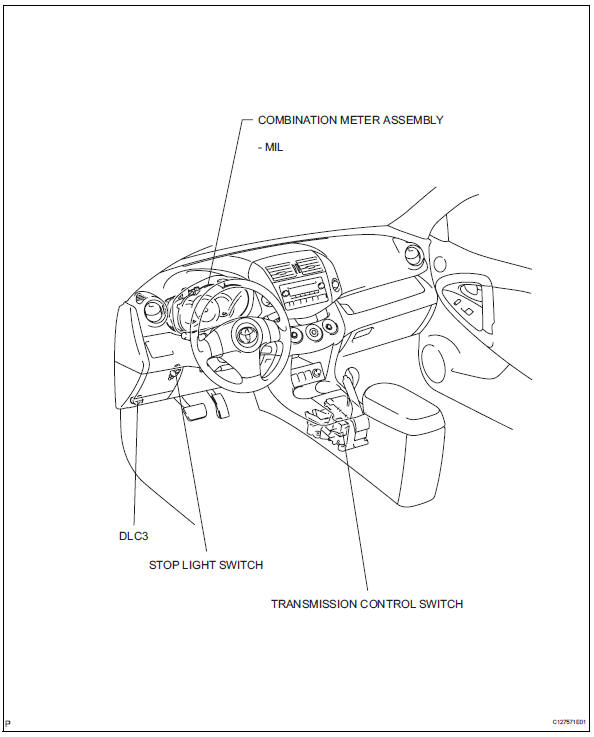
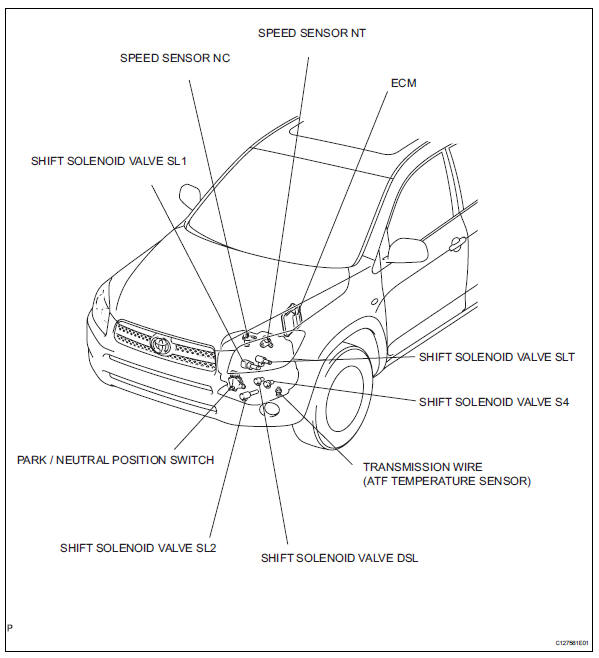
Toyota RAV4 (XA40) 2013-2018 Service Manual: Parts location
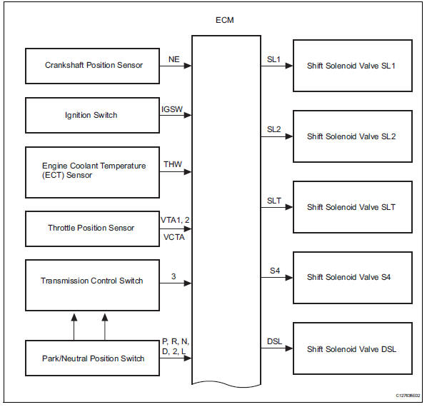
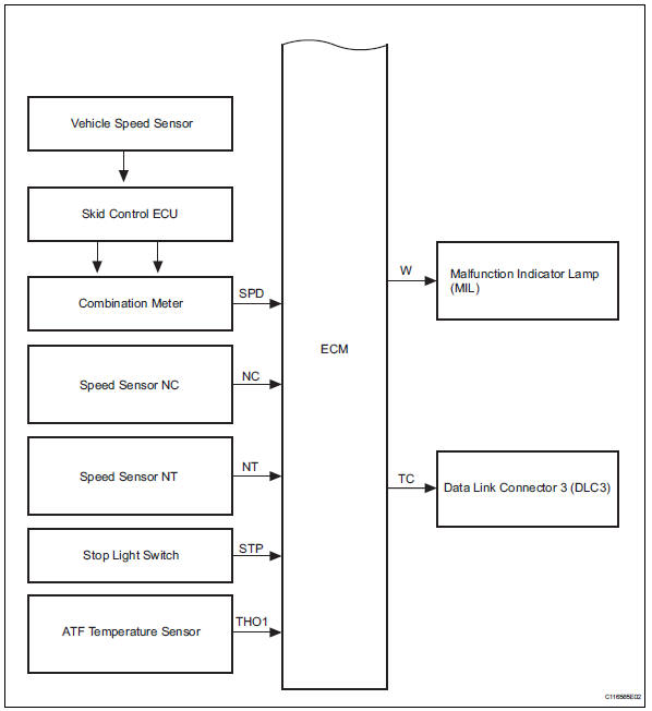
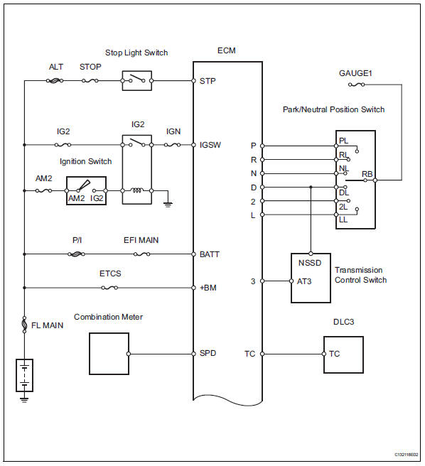
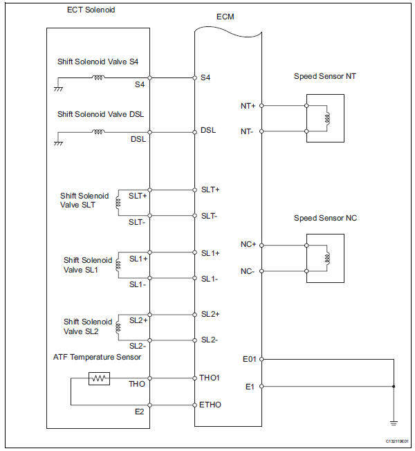
System diagram
The configuration of the electronic control system in the u140f automatic transaxle is as shown in the following chart.
System description
- System description
- The electronic controlled automatic transaxle
(ect) is an automatic transaxle that electronically
controls shift timing using the engine control
module (ecm). The ecm detects electrical signals
that indicate engine and driving conditions, and
controls the shift point based on driver habits and
road conditions. As a result, fuel efficiency and
power transaxle performance are improved.
Shift shock is reduced by controlling the engine and transaxle simultaneously.
In addition, the ect has the following features:
- Diagnostic function.
- Fail-safe function when a malfunction occurs.
How to proceed with troubleshooting
Hint:
- The ecm of this system is connected to the can and multiplex communication system. Therefore, before starting troubleshooting, make sure to check that there is no trouble in the can and multiplex communication systems.
- *: Use the intelligent tester.
- Vehicle brought to workshop

- Customer problem analysis

- Inspect battery voltage
Standard voltage: 11 to 14 v
If the voltage is below 11 v, recharge or replace the battery before proceeding.

- Connect intelligent tester to dlc3*

- Check and clear dtcs and freeze frame data*

- Refer to the dtc check / clear (see page ax-29).
- Visual inspection

- Setting check mode diagnosis*
- Refer to the check mode procedure (see page ax-30).

- Problem symptom confirmation
- Refer to the road test (see page ax-12).
Result 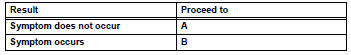

- Symptom simulation
- Refer to the electronic circuit inspection procedure (see page in-37).

- Dtc check*
- Refer to the dtc check / clear (see page ax-29).
Result 

- Basic inspection
- Refer to the automatic transmission fluid (see page ax-102).
- Refer to the park/neutral position switch (see page ax-108).
- Refer to the floor shift assembly (see page ax- 136).

- Mechanical system tests
- Refer to the mechanical system tests (see page ax-15).


- Hydraulic test
- Refer to the hydraulic test (see page ax-16).


- Manual shifting test
- Refer to the manual shifting test (see page ax- 17).


- Problem symptoms table chapter 1
- Refer to the problem symptoms table (see page ax-21).

- Problem symptoms table chapter 2
- Refer to the problem symptoms table (see page ax-21).

- Part inspection

- Dtc chart
- Refer to the diagnostic trouble code chart (see page ax-35).

- Circuit inspection

- Identification of problem

- Repair or replace

- Confirmation test

End
 Precaution
Notice:
Perform the reset memory procedures (a/t
initialization) when replacing the automatic transaxle
assembly, engine assembly or ecm (see page ax-18).
Hint:
Reset memory cannot be completed b ...
 Road test
Problem symptom confirmation
Based on the result of the customer problem
analysis, try to reproduce the symptoms. If the
problem is that the transaxle does not shift up, shift
down, or ...
Other materials:
Canister
Components
removal
Disconnect cable from negative battery
terminal
Caution:
Wait at least 90 seconds after disconnecting the
cable from the negative (-) battery terminal to
prevent airbag and seat belt pretensioner activation.
Remove canister
Disconnect the 2 tubes, hose a ...
If you have a flat tire
Your vehicle is equipped with a spare tire. The flat tire can be
replaced with the spare tire.
For details about tires
Caution
If you have a flat tire
Do not continue driving with a flat tire.
Driving even a short distance with a flat tire can damage the tire and the
wheel beyond repair, ...
Front seats
Adjustment procedure
Manual seat
Seat position adjustment lever
Seatback angle adjustment
lever
Vertical height adjustment
lever (driverŌĆÖs side only)
Power seat (driverŌĆÖs side only)
Seat position adjustment switch
Seatback angle adjustment
switch
seat cushion (f ...
