Toyota RAV4 (XA40) 2013-2018 Service Manual: Front occupant classification sensor rh circuit malfunction
Description
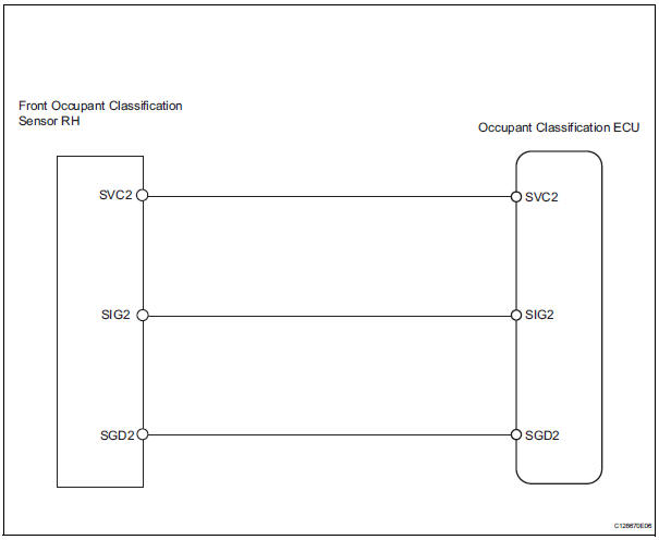
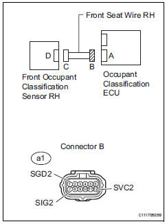
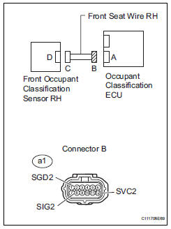
The front occupant classification sensor rh circuit consists of the occupant classification ecu and the front occupant classification sensor rh.
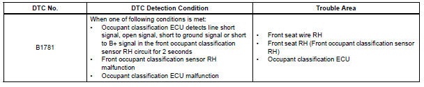
Dtc b1781 is recorded when a malfunction is detected in the front occupant classification sensor rh circuit.
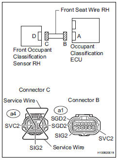
Wiring diagram
Inspection procedure
Hint:
- If troubleshooting (wire harness inspection) is difficult to perform, remove the front passenger seat installation bolts to see the undersurface of the seat cushion.
- In the above case, hold the seat so that it does not tip over. Holding the seat for a long period of time may cause a problem, such as seat rail deformation. Hold the seat up only for as long as necessary.
- Check for dtc
- Turn the ignition switch on.
- Clear the dtcs (see page rs-249).
Hint:
First clear dtcs stored in the occupant classification ecu and then in the center airbag sensor.
- Turn the ignition switch off.
- Turn the ignition switch on.
- Check the dtcs (see page rs-249).
Ok: dtc b1781 is not output.
Hint:
Dtcs other than dtc b1781 may be output at this time, but they are not related to this check.


- Check connection of connector
- Turn the ignition switch off.
- Disconnect the cable from the negative (-) battery terminal, and wait for at least 90 seconds.
- Check that the connectors are properly connected to the occupant classification ecu and the front occupant classification sensor rh.
Ok: the connectors are properly connected.


- Check front seat wire rh (to b+)
- Disconnect the connectors from the occupant classification ecu and the front occupant classification sensor rh.
- Connect the cable to the negative (-) battery terminal, and wait for at least 2 seconds.
- Turn the ignition switch on.
- Measure the voltage of the wire harness side connector.
Standard voltage 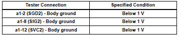

- Check front seat wire rh (for open)
- Turn the ignition switch off.
- Disconnect the cable from the negative (-) battery terminal, and wait for at least 90 seconds.
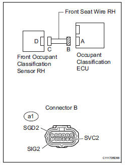
- Using a service wire, connect terminals a4-1 (svc2) and a4-3 (sgd2), and connect terminals a4-2 (sig2) and a4- 3 (sgd2) of connector c.
Notice:
Do not forcibly insert a service wire into the terminals of the connector when connecting them.
- Measure the resistance of the wire harness side connector.
Standard resistance 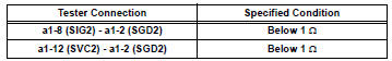

- Check front seat wire rh (for short)
- Disconnect the service wire from connector c.
- Measure the resistance of the wire harness side connector.
Standard resistance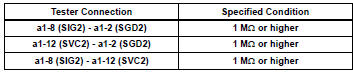

- Check front seat wire rh (to ground)
- Measure the resistance of the wire harness side connector.
Standard resistance 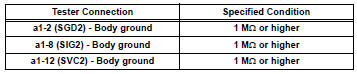

- Check for dtc
- Connect the connectors to the occupant classification ecu and the front occupant classification sensor rh.
- Connect the cable to the negative (-) battery terminal, and wait for at least 2 seconds.
- Turn the ignition switch on.
- Clear the dtcs (see page rs-249).
Hint:
First clear dtcs stored in the occupant classification ecu and then in the center airbag sensor.
- Turn the ignition switch off.
- Turn the ignition switch on.
- Check the dtcs (see page rs-249).
Ok: dtc b1781 is not output.
Hint:
Dtcs other than dtc b1781 may be output at this time, but they are not related to this check.

- Replace occupant classification ecu
- Turn the ignition switch off.
- Disconnect the cable from the negative (-) battery terminal, and wait for at least 90 seconds.
- Replace the occupant classification ecu (see page rs- 392).
Hint:
Perform the inspection using parts from a normal vehicle if possible.

- Perform zero point calibration
- Connect the cable to the negative (-) battery terminal, and wait for at least 2 seconds
- Connect the intelligent tester to the dlc3.
- Turn the ignition switch on.
- Using the intelligent tester, perform the zero point calibration (see page rs-241).
Ok: completed is displayed.


- Perform sensitivity check
- Using the intelligent tester, perform the sensitivity check (see page rs-241).
Standard value: 27 to 33 kg (59.52 To 72.75 Lb)


- Check for dtc
- Connect the cable to the negative (-) battery terminal, and wait for at least 2 seconds.
- Turn the ignition switch on.
- Clear the dtcs (see page rs-249).
Hint:
First clear dtcs stored in the occupant classification ecu and then in the center airbag sensor assembly.
- Turn the ignition switch off.
- Turn the ignition switch on.
- Check the dtcs (see page rs-249).
Ok: dtc b1781 is not output.
Hint:
Dtcs other than dtc b1781 may be output at this time, but they are not related to this check.


- Replace front seat assembly rh
- turn the ignition switch off.
- Disconnect the cable from the negative (-) battery terminal, and wait for at least 90 seconds.
- Replace the front seat rh (see page se-8).

- Perform zero point calibration
- Connect the cable to the negative (-) battery terminal, and wait for at least 2 seconds.
- Connect the intelligent tester to the dlc3.
- Turn the ignition switch on.
- Using the intelligent tester, perform the zero point calibration (see page rs-241).
Ok: completed is displayed.

- Perform sensitivity check
- Using the intelligent tester, perform the sensitivity check (see page rs-241).
Standard value: 27 to 33 kg (59.52 To 72.75 Lb)

End
 Front occupant classification sensor lh circuit
malfunction
Front occupant classification sensor lh circuit
malfunction
Description
The front occupant classification sensor lh circuit consists of the occupant
classification ecu and the
front occupant classification sensor lh.
Dtc b1780 is recorded when a mal ...
 Rear occupant classification sensor lh circuit malfunction
Description
The rear occupant classification sensor lh circuit consists of the occupant
classification ecu and the rear
occupant classification sensor lh.
Dtc b1782 is recorded when a malf ...
Other materials:
Inspection
Inspect starter assembly
Notice:
These tests must be performed within 3 to 5 seconds
to avoid burning out the coil.
Perform the pull-in test.
Disconnect the lead wire from terminal c.
Connect the battery to the magnetic switch as
shown in the illustration. Check that the clutch ...
Throttle actuator control motor current range / performance
Description
The etcs (electronic throttle control system) has a dedicated power supply
circuit. The voltage (+bm)
is monitored and when it is low (less than 4 v), the ecm determines that there
is a malfunction in the
etcs and cuts off the current to the throttle actuator.
When the volt ...
Vehicle lift and support locations
Notice about vehicle condition when
jacking up vehicle
The vehicle must be unloaded before jacking up /
lifting up the vehicle. Never jack up / lift up a heavily
loaded vehicle.
When removing heavy parts such as the engine and
transmission, the center of gravity of the vehicle
m ...
