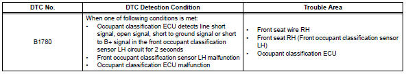
Toyota RAV4 (XA40) 2013-2018 Service Manual: Front occupant classification sensor lh circuit malfunction
Description
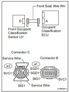
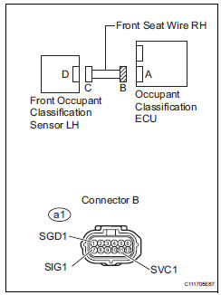
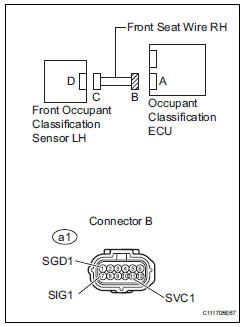
The front occupant classification sensor lh circuit consists of the occupant classification ecu and the front occupant classification sensor lh.
Dtc b1780 is recorded when a malfunction is detected in the front occupant classification sensor lh circuit.
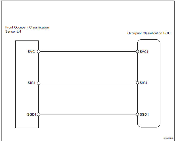
Wiring diagram
Inspection procedure
Hint:
- If troubleshooting (wire harness inspection) is difficult to perform, remove the front passenger seat installation bolts to see the undersurface of the seat cushion.
- In the above case, hold the seat so that it does not tip over. Holding the seat for a long period of time may cause a problem, such as seat rail deformation. Hold the seat up only for as long as necessary.
- Check for dtc
- Turn the ignition switch on.
- Clear the dtcs (see page rs-249).
Hint:
First clear dtcs stored in the occupant classification ecu and then in the center airbag sensor.
- Turn the ignition switch off.
- Turn the ignition switch on.
- Check the dtcs (see page rs-249).
Ok: dtc b1780 is not output.
Hint:
Dtcs other than dtc b1780 may be output at this time, but they are not related to this check.

- Check connection of connector
- Turn the ignition switch off.
- Disconnect the cable from the negative (-) battery terminal, and wait for at least 90 seconds.
- Check that the connectors are properly connected to the occupant classification ecu and the front occupant classification sensor lh.
Ok: the connectors are properly connected.

- Check front seat wire rh (to b+)
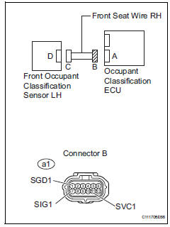
- Disconnect the connectors from the occupant classification ecu and the front occupant classification sensor lh.
- Connect the cable to the negative (-) battery terminal, and wait for at least 2 seconds.
- Turn the ignition switch on.
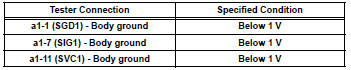
- Measure the voltage of the wire harness side connector.
Standard voltage

- Check front seat wire rh (for open)
- Turn the ignition switch off.
- Disconnect the cable from the negative (-) battery terminal, and wait for at least 90 seconds.
- Using a service wire, connect terminals a2-1 (svc1) and a2-3 (sgd1), and connect terminals a2-2 (sig1) and a2- 3 (sgd1) of connector c.
Notice:
Do not forcibly insert a service wire into the terminals of the connector when connecting them.
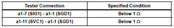
- Measure the resistance of the wire harness side connector.
Standard resistance

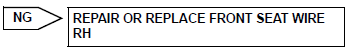
- check front seat wire rh (for short)
- Disconnect the service wire from connector c.
- Measure the resistance of the wire harness side connector
Standard resistance 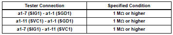

- Check front seat wire rh (to ground)
- Measure the resistance of the wire harness side connector.
Standard resistance 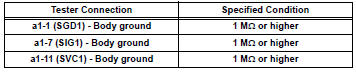

- Check for dtc
- Connect the connectors to the occupant classification ecu and the front occupant classification sensor lh.
- Connect the cable to the negative (-) battery terminal, and wait for at least 2 seconds.
- Turn the ignition switch on.
- Clear the dtcs (see page rs-249).
Hint:
First clear dtcs stored in the occupant classification ecu and then in the center airbag sensor.
- Turn the ignition switch off.
- Turn the ignition switch on.
- Check the dtcs (see page rs-249).
Ok: dtc b1780 is not output.
Hint:
Dtcs other than dtc b1780 may be output at this time, but they are not related to this check.

- Replace occupant classification ecu
- Turn the ignition switch off.
- Disconnect the cable from the negative (-) battery terminal, and wait for at least 90 seconds.
- Replace the occupant classification ecu (see page rs- 392).
Hint:
Perform the inspection using parts from a normal vehicle if possible.

- Perform zero point calibration
- Connect the cable to the negative (-) battery terminal, and wait for at least 2 seconds.
- Connect the intelligent tester (with can vim) to the dlc3.
- Turn the ignition switch on.
- Using the intelligent tester, perform the zero point calibration (see page rs-241).
Ok: completed is displayed.

- Perform sensitivity check
- Using the intelligent tester, perform the sensitivity check (see page rs-241).
Standard values: 27 to 33 kg (59.52 To 72.75 Lb)

- Check for dtc
- Connect the cable to the negative (-) battery terminal, and wait for at least 2 seconds.
- Turn the ignition switch on.
- Clear the dtcs (see page rs-249).
Hint:
First clear dtcs stored in the occupant classification ecu and then in the center airbag sensor.
- Turn the ignition switch off.
- Turn the ignition switch on.
- Check the dtcs (see page rs-249).
Ok: dtc b1780 is not output.
Hint:
Codes other than dtc b1780 may be output at this time, but they are not related to this check.

- Replace front seat assembly rh
- Turn the ignition switch off.
- Disconnect the cable from the negative (-) battery terminal, and wait for at least 90 seconds.
- Replace the front seat rh (see page se-11).

- Perform zero .on
- Connect the cable to the negative (-) battery terminal, and wait for at least 2 seconds.
- Connect the intelligent tester to the dlc3.
- Turn the ignition switch on.
- Using the intelligent tester, perform the zero point calibration (see page rs-241).
Ok: completed is displayed.

- Perform sensitivity check
- Using the intelligent tester, perform the sensitivity check (see page rs-241).
Standard value: 27 to 33 kg (59.52 To 72.75 Lb)

End
 Passenger side buckle switch circuit malfunction
Description
The passenger side buckle switch circuit consists of the occupant
classification ecu and the front seat
inner belt rh.
Dtc b1771 is recorded when a malfunction is detected in th ...
 Front occupant classification sensor rh circuit malfunction
Description
The front occupant classification sensor rh circuit consists of the occupant
classification ecu and the
front occupant classification sensor rh.
Dtc b1781 is recorded when a mal ...
Other materials:
Terminals of ecu
Check combination meter assembly
Disconnect the e19 meter connector.
Measure the voltage and resistance of the wire
harness side connector.
If the result is not as specified, there may be a
malfunction on the wire harness side.
Check heater control panel (for automat ...
Screen for general settings
Press the “setup” button.
Select “general” on the “setup”
screen.
“English”, “français” or
“español” can be selected.
On/off can be selected to
sound beeps.
Select to change the screen
color.
Select to change the keyboard
layout.
...
Hill-start assist control
When the engine is stopped by
the Stop & Start system when
the vehicle is on an incline,
when the brake pedal is
released, brake force is temporarily
maintained to prevent the
vehicle from rolling backwards
before the engine is restarted
and drive force is generated.
When drive force is generat ...
