Toyota RAV4 (XA40) 2013-2018 Service Manual: Room temperature sensor (for automatic ai conditioning system)
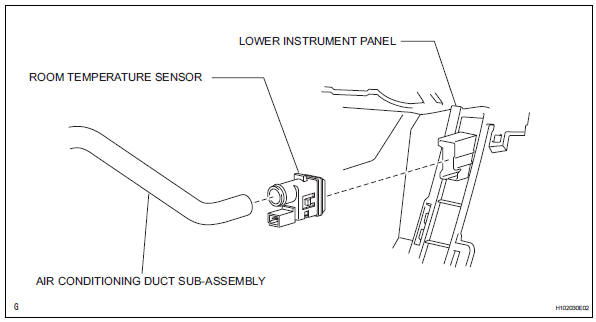
Components
Removal
- Remove lower instrument panel
- Remove the lower instrument panel (see page ip- 16).
- Remove room temperature sensor
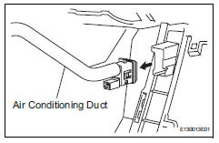
- Disconnect the duct.
- Disconnect the connector.
- Detach the claws and remove the sensor.
Inspection
- Inspect room temperature sensor
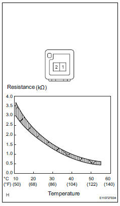
- Measure the resistance of the sensor.
Standard resistance 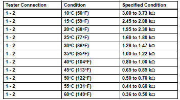
Notice:
- Touching the sensor even slightly may change the resistance value. Hold the connector of the sensor.
- When measuring the resistance, the sensor temperature must be the same as the ambient temperature.
Hint:
As the temperature increases, the resistance decreases (see the graph).
If the result is not as specified, replace the room temperature sensor.
Installation
- Install room temperature sensor
- Attach the claws to install the sensor.
- Connect the connector.
- Connect the duct.
- Install lower instrument panel
- Install the lower instrument panel (see page ip-23).
Installation
- Install ambient temperature sensor
- Connect the connector, and then push in the sensor.
- Install front bumper cover
- Install the front bumper cover (see page et-10).
- Connect cable to negative battery terminal
- Check srs warning light
- Check srs warning light (see page rs-37).
 Condenser
Components
On-vehicle inspection
Inspect cooler condenser assembly
If the fins of the cooler condenser are dirty, clean
them with water. Dry the fins with compressed air.
Notic ...
 Evaporator temperatur sensor
Removal
Remove air conditioning unit
Remove the air conditioning radiator (see page ac-
185).
Remove evaporator temperature sensor
(see page ac-193)
Inspection
Inspect evapo ...
Other materials:
Installation
Install rear differential support
Install the differential support to the differential
carrier with the 4 bolts.
Torque: 98 n*m (999 kgf*cm, 72 ft.*Lbf)
Install rear differential no. 1 And no. 2 Support
Install the differential no. 1 And no. 2 Supports with
the 4 bo ...
Data list / active test
Read data list
Hint:
Using the intelligent tester's data list allows switch,
actuator and other item values to be read without
removing any parts. Reading the data list early in
troubleshooting is one way to save time.
Connect the intelligent tester (with can vim) to the
dlc3.
Turn ...
Rear wheel alignment
adjustment
Inspect tire
Inspect the tire (see page tw-1).
Measure vehicle height
Measure the vehicle height (see page sp-3).
Inspect toe-in
Standard toe-in
If the toe-in is not within the specified range, inspect the
suspension parts and replace them if necessar ...
