Toyota RAV4 (XA50) 2019-2026 Owners Manual: Checking and replacing fuses
If any of the electrical components do not operate, a fuse may have blown. If this happens, check and replace the fuses as necessary.
Checking and replacing fuses
1. Turn the engine switch to OFF.
2. Open the fuse box cover.
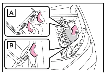
Engine compartment: Type A fuse box (if equipped)
Push claws A and B to completely release the lock, and then lift up the cover.
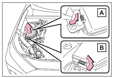
Engine compartment: Type B fuse box
Push claws A and B to completely release the lock, and then lift up the cover.
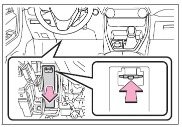
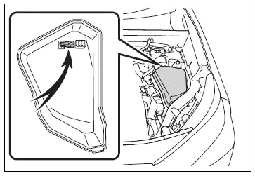
Left side instrument panel
Remove the lid.
3. Remove the fuse.
Only type A fuse can be removed using the pullout tool.
4. Check if the fuse is blown.
Replace the blown fuse with a new fuse of an appropriate amperage rating. The amperage rating can be found on the fuse box lid.
Type A
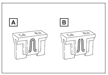
- Normal fuse
- Blown fuse
Type B
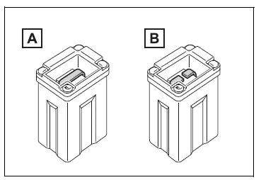
- Normal fuse
- Blown fuse
Type C
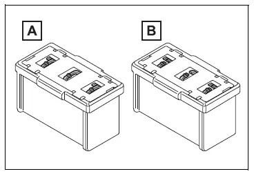
- Normal fuse
- Blown fuse
â– After a fuse is replaced
- When installing the lid, make sure that the tab is installed securely.
- If the lights do not turn on even after the fuse has been replaced, a bulb may need replacement.
- If the replaced fuse blows again, have the vehicle inspected by your Toyota dealer.
â– If there is an overload in a circuit
The fuses are designed to blow, protecting the wiring harness from damage.
WARNING
â– To prevent system breakdowns and vehicle fire
Observe the following precautions.
Failure to do so may cause damage to the vehicle, and possibly a fire or injury.
- Never use a fuse of a higher amperage rating than that indicated, or use any other object in place of a fuse.
- Always use a genuine Toyota
fuse or equivalent.
Never replace a fuse with a wire, even as a temporary fix.
- Do not modify the fuses or fuse boxes.
NOTICE
â– Before replacing fuses
Have the cause of electrical overload determined and repaired by your Toyota dealer as soon as possible.
NOTICE
â– To prevent damage to the engine compartment fuse box cover
When opening the fuse box, completely release the claw locks before lifting up the cover. Otherwise, the claws may be damaged.
 Wireless remote control/electronic key battery
Replace the battery with a
new one if it is depleted.
â– If the key battery is depleted
The following symptoms may occur:
The smart key system (if
equipped) and wireless remote
control will not fu ...
 Headlight aim
Vertical movement adjusting
bolts
Adjustment bolt A
Adjustment bolt B
Before checking the headlight
aim
Make sure the vehicle has a
full tank of gasoline and the
area around the headlight is
...
Other materials:
Traction control switch (for 2wd)
Components
Removal
Disconnect cable from negative battery
terminal
Caution:
Wait at least 90 seconds after disconnecting the
cable from the negative (-) battery terminal to
prevent airbag and seat belt pretensioner activation.
Remove traction control switch (auto lsd switch)
...
BSM (Blind Spot Monitor)
The Blind Spot Monitor is a
system that uses rear side
radar sensors installed on
the inner side of the rear
bumper on the left and right
side to assist the driver in
confirming safety when
changing lanes.
WARNING
â– Cautions regarding the use of
the system
The driver is solely responsible
for sa ...
Trailer Tongue Weight
A recommended tongue
weight varies in accordance
with the types of trailers or
towing as described below.
To ensure the recommended
values shown below, the
trailer must be loaded by
referring to the following
instructions.
Tongue Weight
The gross trailer weight should be
distribut ...
