Toyota RAV4 (XA40) 2013-2018 Owners Manual: Child restraint systems with a top tether strap
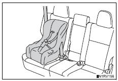
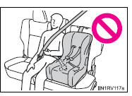
- Secure the child restraint system
using the seat belt or
latch anchors.
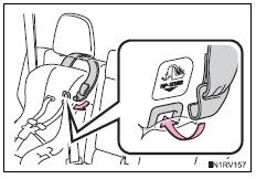
- Latch the hook onto the anchor
bracket and tighten the top
tether strap.
Make sure the top tether strap is securely latched.
Laws and regulations pertaining to anchorages
The latch system conforms to fmvss225 or cmvss210.2.
Child restraint systems conforming to fmvss213 or cmvss213 specifications can be used.
This vehicle is designed to conform to the sae j1819.
Caution
When installing a booster seat
To prevent the belt from going into alr lock mode, do not fully extend the shoulder belt. Alr mode causes the belt to tighten only. This could cause injury or discomfort to the child.
When installing a child restraint system
- Follow the directions given in the child restraint system installation
manual
and fix the child restraint system securely in place.
If the child restraint system is not correctly fixed in place, the child or other passengers may be seriously injured or even killed in the event of sudden braking, sudden swerving or an accident.
- If the driverŌĆÖs seat interferes with the child restraint system and prevents it from being attached correctly, attach the child restraint system to the right-hand rear seat.
- Adjust the front passenger seat so that
it does not interfere with the child
restraint system.
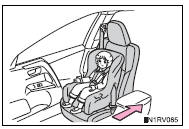
- Only put a forward-facing child restraint
system on the front seat when unavoidable.
When installing a forward-facing child restraint system on the front passenger seat, move the seat as far back as possible even if the ŌĆ£air bag offŌĆØ indicator light is illuminated. Failure to do so may result in death or serious injury if the airbags deploy (inflate).
When installing a child restraint system
- When installing a child restraint system in the rear center seat, adjust both seatbacks at the same angle. Otherwise, the child restraint system cannot be securely restrained and this may cause death or serious injuries in the event of sudden braking, sudden swerving or an accident.
- When a booster seat is installed, always ensure that the shoulder belt is positioned across the center of the childŌĆÖs shoulder. The belt should be kept away from the childŌĆÖs neck, but not so that it could fall off the childŌĆÖs shoulder. Failing to do so may result in death or serious injury in the event of sudden braking, sudden swerving or an accident.
- Ensure that the belt and plate are securely locked and the seat belt is not twisted.
- Shake the child restraint system left and right, and forward and backward to ensure that it has been securely installed.
- After securing a child restraint system, never adjust the seat.
- Follow all installation instructions provided by the child restraint system manufacturer.
- When using the left side seat for the
child restraint system, do not sit in the
center seat. Seat belt function may be
impaired, such as being positioned
overly high or loose-fitting, which may
result in death or serious injury in the
event of sudden braking or an accident.
Caution
Do not use a seat belt extender
If a seat belt extender is used when installing a child restraint system, the seat belt will not securely hold the child restraint system, which could cause death or serious injury to the child or other passengers in the event of a sudden braking, sudden swerving or an accident.
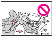
To correctly attach a child restraint system to the anchors
When using the latch anchors, be sure that there are no foreign objects around the anchors and that the seat belt is not caught behind the child restraint system. Make sure the child restraint system is securely attached, or it may cause death or serious injury to the child or other passengers in the event of sudden braking, sudden swerving or an accident.
 Installing child restraints using a seat belt (child restraint lock
function belt)
Installing child restraints using a seat belt (child restraint lock
function belt)
Rear-facing ŌĆ×o infant seat/convertible seat
Adjust the seatback to the
8th lock position from the
fully reclined position.
Fully reclined position
8Th lock position
If your ch ...
 Exhaust gas precautions
Harmful substance to the human body is included in exhaust
gases if inhale.
Caution
Exhaust gases include harmful carbon monoxide (co), which is colorless and
odorless. Observe the following preca ...
Other materials:
Changing the display
The multi-information display is
operated using the meter control
switches.
Scroll the screen*/switch the
display*/move the cursor
Press: Enter/Set
Press and hold: Reset/Display
customizable items
Return to the previous screen
Call sending/receiving and
history display (if equipped)
Linke ...
Refueling
Opening the fuel tank cap
Perform the following steps
to open the fuel tank cap:
Before refueling the vehicle
Close all the doors and windows,
and turn the engine
switch to OFF.
Confirm the type of fuel.
Ō¢ĀFuel tank opening for unleaded
gasoline
To help prevent incorrect fueling,
your vehicle ...
Before driving
Floor mat
Use only floor mats designed specifically for vehicles of the same
model and model year as your vehicle. Fix them securely in place
onto the carpet.
Insert the retaining hooks (clips)
into the floor mat eyelets.
Turn the upper knob of each
retaining hook (clip) to secure
t ...
