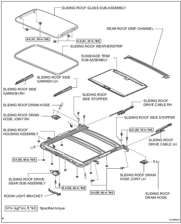
Toyota RAV4 (XA40) 2013-2018 Service Manual: Components (2005/11-2006/01)
Sliding roof ecu power source circuit
Description
If the sliding function and tilt function do not operate, there may be a malfunction in the sliding roof ecu power source circuit.
Wiring diagram
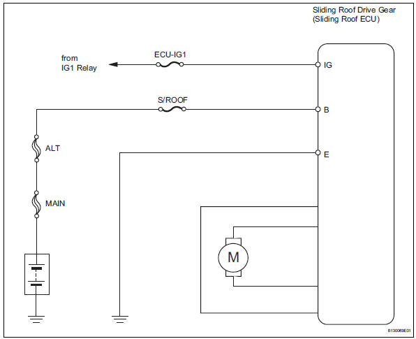
Inspection procedure
- Perform active test by intelligent tester (sliding roof operation)
- Select the active test, use the intelligent tester to generate a control command, and then check that the sliding roof operates normally.
Sliding roof ecu
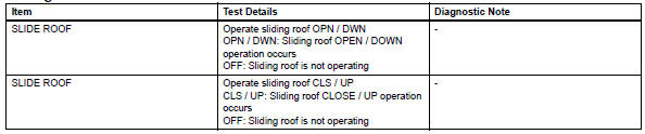
Ok: sliding roof operates normally.

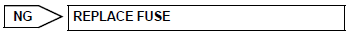
- Inspect fuse (s/roof, ecu-ig1)
- Remove the s/roof and ecu-ig1 fuses from the instrument panel junction block.
- Measure the resistance of the fuses.
Standard resistance:
below 1 

- Check wire harness (sliding roof drive gear - body ground)
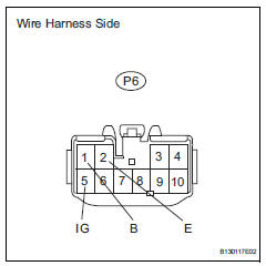
- Disconnect the p6 drive gear connector.
- Measure the voltage and resistance of the wire harness side connector.
Standard voltage 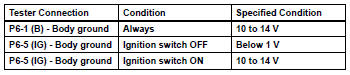
Standard resistance 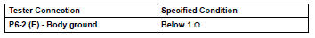

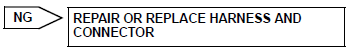
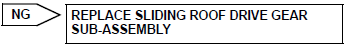
Replace sliding roof drive gear sub-assembly


Other materials:
Diagnostic trouble code chart
Hint:
If any dtcs are displayed during the dtc check, inspect the
circuit listed for these dtcs. For details of each dtc, refer to
the page indicated in the dtc chart.
Hint:
: Warning
light comes on
X: warning light turns off (normal reset) ...
Luggage compartment
features
Cargo hooks
Raise the hooks to use.
The cargo hooks are provided for
securing loose items.
Caution
When the cargo hooks are not in use
To avoid injury, always return the cargo hooks to their stowed
positions.
Grocery bag hooks
Notice
Grocery bag hook weight capacity
Do not hang ...
Ecu malfunction
Description
Inspection procedure
If the power steering ecu detects these dtcs, it will shut off the motor
relay circuit (built into the power
steering ecu) and stop power assist. However, power assist continues if dtc
c1533 is output.
Reconfirm dtc
Check for dtc.
Ok:
dtc i ...
