Toyota RAV4 (XA40) 2013-2018 Service Manual: Diagnosis system
- Description
The occupant classification ecu controls the functions of the occupant classification system on the vehicle. Data of the occupant classification system can be read in the data link connector 3 (dlc3) of the vehicle. When the system seems to be malfunctioning, use the intelligent tester to check for a malfunction and perform repairs.
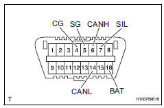
- Check dlc3
The ecu uses iso 15765-4 for communication. The terminal arrangement of the dlc3 complies with iso 15031-3 and matches the iso 15765-4 format.
Notice:
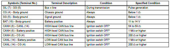
*: Before measuring the resistance, leave the vehicle as is for at least 1 minute and do not operate the ignition switch, any switches or doors.
If the result is not as specified, the dlc3 may have a malfunction. Repair or replace the harness and connector.
Hint:
Connect the cable of the intelligent tester (with can vim) to the dlc3, turn the ignition switch on and attempt to use the tester. If the display indicates that a communication error has occurred, there is a problem either with the vehicle or with the tester.
- If communication is normal when the tester is connected to another vehicle, inspect the dlc3 on the original vehicle.
- If communication is still not possible when the tool is connected to another vehicle, the problem is probably in the tester itself. Consult the service department listed in the tester's instruction manual.
- Symptom simulation
Hint:
The most difficult case in troubleshooting is when no symptoms occur. In such cases, a thorough customer problem analysis must be carried out. A simulation of the same or similar conditions and environment in which the problem occurred in the customer's vehicle should be carried out. No matter how much skill or experience a technician has, troubleshooting without confirming the problem symptoms will lead to important repairs being overlooked and mistakes or delays.
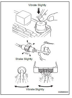
- Vibration method:
When vibration seems to be the major cause.
Hint:
Perform the simulation method only during the primary check period (for approximately 6 seconds after the ignition switch is turned on).
- Slightly vibrate the part of the sensor considered to be the cause of the problem with your fingers and check whether the malfunction occurs.
Hint:
Shaking the relays too strongly may result in open relays.
- Slightly shake the connector vertically and horizontally.
- Slightly shake the wire harness vertically and horizontally.
The connector joint and fulcrum of the vibration are the major areas to be checked thoroughly.
- Simulation method for dtc b1795:
Turn the ignition switch from the lock to the on position, hold the position for 10 seconds, and then turn it back to the lock position again 50 times in a row.
Hint:
Dtc b1795 is output if the occupant classification ecu receives the ignition switch lock-on-lock signal 50 times in a row when a malfunction occurs in the power circuit for the occupant classification system.
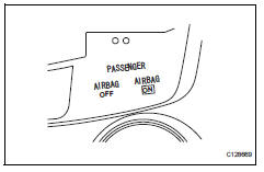
- Function of passenger airbag on/off indicator
- Initial check
- Turn the ignition switch on.
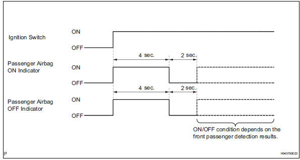
- The passenger airbag on/off indicator (on and off) comes on for approximately 4 seconds, then goes off for approximately 2 seconds.
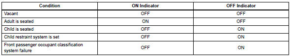
- Approximately 6 seconds after the ignition switch is turned to the on position, the passenger airbag on/off indicator will be on/ off depending on the conditions listed below.
Hint:
- The passenger airbag on/off indicator operates based on the timing chart below in order to check the indicator light circuit.
- When the occupant classification system has trouble, both the srs warning light and the passenger airbag off indicator (off) come on. In this case, check the dtcs in the airbag system first.
- Check passenger airbag on/off indicator
- Turn the ignition switch on.
- Check that the passenger airbag on/off indicators come on for approximately 4 seconds, then go off for approximately 2 seconds.
Hint:
Refer to the table in the previous step regarding the passenger airbag on/off indicator when approximately 6 seconds have elapsed after the ignition switch is turned to the on position.
 Terminals of ecu
Check occupant classification ecu
Measure the voltage of the connector.
...
 Dtc check / clear
Check dtc
Hint:
When dtc b1650/23 is detected as a result of
troubleshooting for the airbag system, troubleshoot
the occupant classification system.
Use the intelligent tester (with ca ...
Other materials:
Pressure control solenoid "A" electrical (shift solenoid valve sl1)
Description
Shifting from 1st to o/d is performed in combination with the on and off
operation of the shift solenoid
valves sl1 and sl2, which are controlled by the ecm. If an open or short circuit
occurs in any of the shift
solenoid valves, the ecm controls the remaining normal shift soleno ...
LTA (Lane Tracing Assist)
While driving on a road with
clear white (yellow) lane
lines, the LTA system warns
the driver if the vehicle may
deviate from the current
lane or course*, and also
can slightly operate the
steering wheel to help avoid
deviation from the lane or
course*. Also, while the
dynamic radar cruise control
w ...
System description
General
The air conditioning system has the following
features:
The air conditioning amplifier controls the
operation of parts, such as the a/c compressor,
automatically in accordance with the operating
conditions of the air conditioning system.
Mode position and damper ...
