Toyota RAV4 (XA40) 2013-2018 Service Manual: Diagnosis system
- Description
- Air conditioning system data and the diagnostic trouble codes (dtcs) can be read through the data link connector 3 (dlc3) of the vehicle. When the system seems to be malfunctioning, use the intelligent tester to check for malfunctions and perform troubleshooting.
- Check dlc3
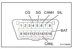
The vehicle's ecm uses the iso 15765-4 for communication protocol. The terminal arrangement of the dlc3 complies with sae j1962 and matches the iso 15765-4 format.
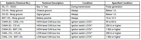
If the result is not as specified, the dlc3 may have a malfunction. Repair or replace the harness and connector.
Notice:
*: Before measuring the resistance, leave the vehicle as is for at least 1 minute and do not operate the ignition switch, other switches or doors.
Hint:
Connect the cable of the intelligent tester (with can vim) to the dlc3, turn the ignition switch on and attempt to use the tester. If the display indicates that a communication error has occurred, there is a problem either with the vehicle or with the tester.
If communication is normal when the tester is connected to another vehicle, inspect the dlc3 of the original vehicle.
If communication is still not possible when the tester is connected to another vehicle, the problem may be in the tester itself. Consult the service department listed in the tester's instruction manual.
 Terminals of ecu (2006/01- )
Check air conditioning amplifier
Measure the voltage and resistance of the
connectors.
Hint:
Check from the rear of the connector while it is
connected to the air conditioning ampl ...
 Dtc check / clear
Check dtc
Connect the intelligent tester (with can vim) to the
dlc3.
Turn the ignition switch on and turn the intelligent
tester on.
Read the dtc by following the prompts on the
...
Other materials:
Installation
Install knock sensor
Install the sensor with the nut.
Torque: 20 n*m (205 kgf*cm, 15 ft.*Lbf)
Notice:
Make sure that the knock sensor is in the
correct position.
Connect the sensor connector.
Install intake manifold insulator
install the intake manifold insulat ...
Rear brake
Components
Removal
Hint:
Use the same procedures for the lh side and rh side.
The procedures listed below are for the lh side.
Remove rear wheel
Drain brake fluid
Notice:
Wash off brake fluid immediately if it comes in
contact with any painted surface.
Disconnect rea ...
Evaporative emission control system pressure sensor
Dtc summary
Hint:
The canister pressure sensor is built into the canister pump module.
Description
The description can be found in the evap (evaporative emission) system (see
page es-335).
Monitor description
Dtc p0450: canister pressure sensor abnormal fluctuation
If t ...
