Toyota RAV4 (XA40) 2013-2018 Service Manual: Differential case
Components
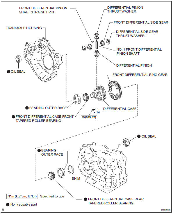
Disassembly
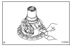
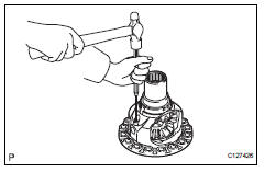
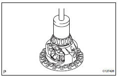
- Remove front differential ring gear
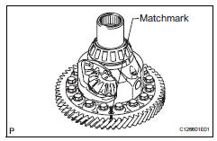
- Place the matchmarks on the ring gear and differential case.
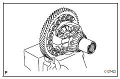
- Remove the 14 bolts.
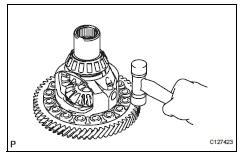
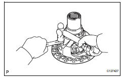
- Using a plastic-faced hammer, tap on the ring gear to remove it from the case.
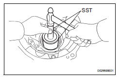
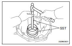
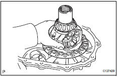
- Remove front differential case front tapered roller bearing
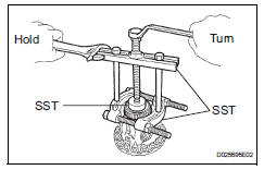
- Using sst, tap out the front differential case front tapered roller bearing from the differential case.
Sst 09950-00020, 09950-00030, 09950-60010 (09951-00500)
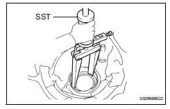
- Using sst, remove the front differential case front tapered roller bearing outer race.
Sst 09308-00010
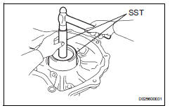
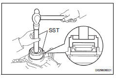
- Remove front differential case rear tapered roller bearing
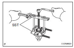
- Using sst, remove the front differential case rear tapered roller bearing from the differential case.
Sst 09950-00020, 09950-00030, 09950-60010 (09951-00500)
- Using sst, tap out the front differential case front tapered roller bearing outer race.
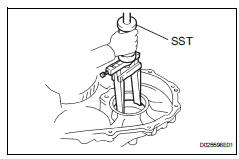
Sst 09308-00010
- Remove front differential pinion shaft straight pin
- Using a pin punch and hammer, tap in the straight pin.
Notice:
Before removing the straight pin, unstake it with a pin punch.
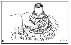
- Remove no. 1 Front differential pinion shaft
- Remove the front differential pinion shaft from the differential case.
- Remove front differential side gear
- Remove the 2 front differential pinions, 2 pinion thrust washers, 2 front differential side gears and 2 side gear thrust washers from the differential case.
- Remove transaxle housing oil seal
- Using sst and hammer, tap out the oil seal.
Sst 09950-70010 (09951-07100), 09215-00013 (09215-00471)
- Remove differential side bearing retainer oil seal
- Using sst and hammer, tap out the oil seal.
Sst 09950-70010 (09951-07100), 09608-10010
Inspection
- Inspect differential side gear backlash
- Using a dial indicator, measure the backlash of the side gear.
Standard backlash: 0.05 To 0.20 Mm (0.0020 To 0.0070 In.)
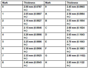
Standard thrust washer thickness
Reassembly
- Install front differential side gear
- Coat the 2 front differential side gears, 2 side gear thrust washers, 2 font differential pinions and 2 pinion thrust washers with atf and install them to the differential case.
- Install no. 1 Front differential pinion shaft
- Coat the no. 1 Front differential pinion shaft with atf, and install it to the differential case.
- Install transaxle case straight pin
- Using a pin punch and a hammer, tap in the pinion shaft straight pin.
- Using a chisel and a hammer, stake the differential case.
Notice:
Stake it after adjusting the backlash.
- Install front differential case rear tapered roller bearing
- Using sst and a press, press in the front differential case rear tapered roller bearing to the differential case.
Sst 09550-60010, 09950-60020 (09951-00680), 09950-70010 (09951-07100)
- Using sst and a hammer, tap in the front differential case tapered roller bearing front outer race to the transaxle housing.
Sst 09550-60010, 09950-60020 (09951-00680), 09950-70010 (09951-07100, 09951-00890)
- Install front differential case front tapered roller bearing
- Using sst and a press, press in the front differential case rear tapered roller bearing to the differential case.
Sst 09550-60010, 09950-60020 (09951-00680), 09950-70010 (09951-07100, 09951-00890)
- Using sst and a hammer, tap in the front differential case tapered roller bearing front outer race to the transaxle housing.
Sst 09550-60010, 09950-60020 (09951-00680), 09950-70010 (09951-07100, 09951-00890)
Notice:
Clearance is not allowed between the bearing and transaxle housing.
- Adjust differential side bearing preload
- Install the differential assembly to the transaxle case.
- Clean the matching surfaces of the transaxle case and transaxle housing.
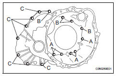
- Install the transaxle housing to the transaxle case and tighten them with the 16 bolts
Torque: 22 n*m (224 kgf*cm, 16 ft.*Lbf) for bolt a 29 n*m (296 kgf*cm, 21 ft.*Lbf) for bolts b and c
Hint:
Each bolt length is indicated below.
Bolt length:
50 Mm (1.969 In.) For bolt a
50 M (1.969 In.) For bolt b
42 Mm (1.654 In.) For bolt c
Notice:
Usually, bolt a is non-reusable bolt. In this case, however, it can be used after cleaning it.
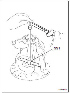
- Using sst, return the differential assembly right and left 2 or 3 times to allow the bearing settle.
Sst 09564-32011
- Using sst and torque wrench, measure the turning torque of the differential.
Sst 09564-32011
Torque: standard turning torque at 60 rpm 0.20 To 0.69 N*m (2.0 To 7.0 Kgf*cm, 1.8 To 6.1 In.*Lbf)
Hint:
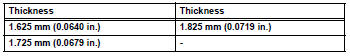
If the turning torque is not within the specified value, refer to the table below and select a thrust washer which turning torque is within the specified value.
Standard flange thickness
- Remove the 16 bolts and the transaxle housing.
- Remove the differential assembly.
- Install front differential ring gear
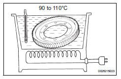
- Using atf and a heater, heat the front differential ring gear to 90 to 110 °c (194.0 To 230.0 °F)
Notice:
Do not overheat the ring gear to 110°c (230.0°F) or more.
- Clean the contract surface of the front differential case.
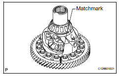
- Align the matchmarks, and install the front differential ring gear case quickly.
Notice:
Do not install the bolts while the ring gear is hot.
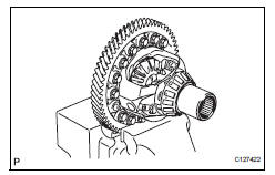
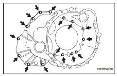
- Tighten the 14 bolts.
Torque: 95 n*m (969 kgf*cm, 70 ft.*Lbf)
Notice:
Tighten the bolts a little at a time in diagonal order.
- Install differential side bearing retainer oil seal
- Coat the lip of a new oil seal with a little amount of mp grease.
- Using sst and a hammer, tap in the oil seal.
Sst 09223-15020, 09950-70010 (09951-07100)
- Remove transaxle housing oil seal
- Coat the lip of a new oil seal with a little amount of mp grease.
- Using sst and a hammer, tap in the oil seal.
Sst 09710-30050, 09950-70010 (09951-07100)
 Valve body
Components
Disassembly
Remove shift solenoid valve slt
Remove the bolt, plate and shift solenoid valve slt
from the valve body.
Remove shift solenoid valve sl1
Rem ...
 Instrument panel
...
Other materials:
Removal
Table of bolt, screw and nut
Hint:
All bolts, screws and nuts relevant to installing and
removing the instrument panel are shown along with
their alphabet codes in the table below.
Disconnect cable from negative battery
terminal
Caution:
Wait at least 90 seconds after disconne ...
Utility vehicle
precautions
This vehicle belongs to the utility vehicle class, which has
higher ground clearance and narrower tread in relation to the
height of its center of gravity to make it capable of performing in
a wide variety of off-road applications.
Utility vehicle feature
Specific design characteristics give ...
Removal
Remove radiator grille sub-assembly
Remove the 4 bolts and 4 nuts.
Detach the 6 claws and remove the radiator grille.
Remove no. 1 Radiator grille lower
Detach the 16 claws and remove the radiator grille.
Remove no. 2 Radiator grille lower
Detac ...
