Toyota RAV4 (XA40) 2013-2018 Service Manual: Check 4wd control ecu (for 4wd)
Notice:
- Turn the ignition switch off before measuring the resistances of the main wire and branch wire.
- After the ignition switch is turned off, check that the key reminder warning system and light reminder warning system are not in operation.
- Before measuring the resistance, leave the vehicle as is for at least 1 minute and do not operate the ignition switch, any other switches or the doors. If doors need to be opened in order to check connectors, open the doors and leave them open.
Hint:
Operating the ignition switch, any other switches or the doors triggers related ecu and sensor communication with the can, which causes resistance variation.
- Junction connector
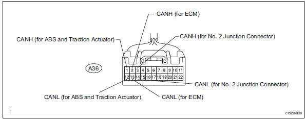
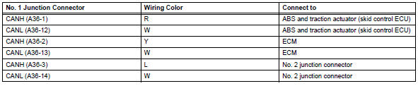
- No. 1 Junction connector
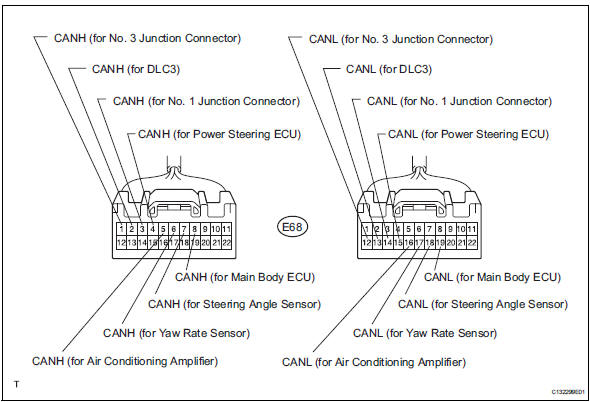
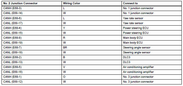
- No. 2 Junction connector
- No. 3 Junction connector
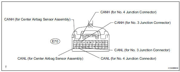
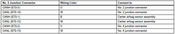
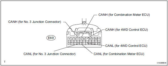
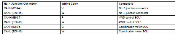
- No. 4 Junction connector
Hint:
*: For 4wd
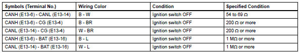
- Check dlc3
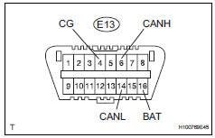
- Measure the resistance of the connector.
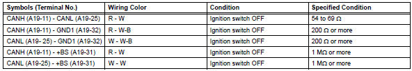
- Check abs and traction actuator (skid control ecu)
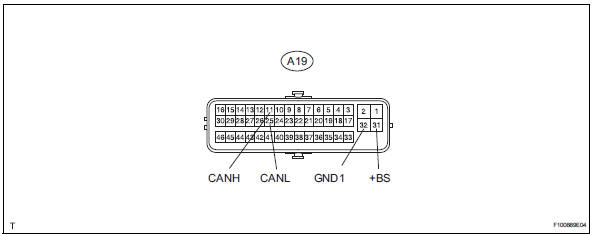
- Disconnect the a19 ecu connector.
- Measure the resistance of the wire harness side connector.
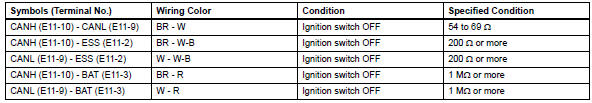
- Check steering angle sensor
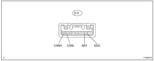
- Disconnect the e11 sensor connector.
- Measure the resistance of the wire harness side connector.
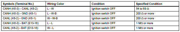
- Check yaw rate sensor
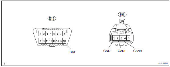
- Disconnect the k6 sensor connector.
- Measure the resistance of the wire harness side connector.
- Check air conditioning amplifier (for automatic air conditioning system)
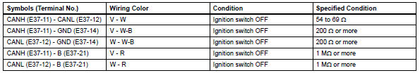
- Disconnect the e37 amplifier connector.
- Measure the resistance of the wire harness side connector.
- Check air conditioning amplifier (for manual air conditioning system)
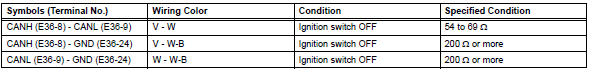
- Disconnect the e36 amplifier connector.
- Measure the resistance of the wire harness side connector.

- Check ecm
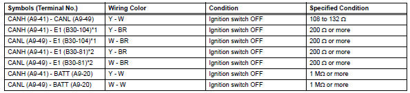
- Disconnect the a9 and b30 ecm connectors.
- Measure the resistance of the wire harness side connectors.
Hint:
*1: For 2az-fe
*2: For 2gr-fe
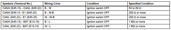
- Check center airbag sensor assembly
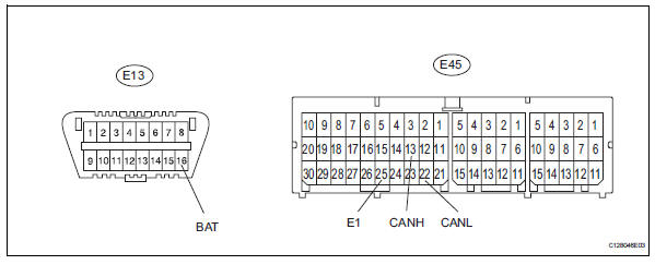
- Disconnect the e45 sensor connector.
- Measure the resistance of the wire harness side connectors.
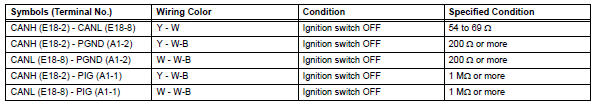
- Check power steering ecu
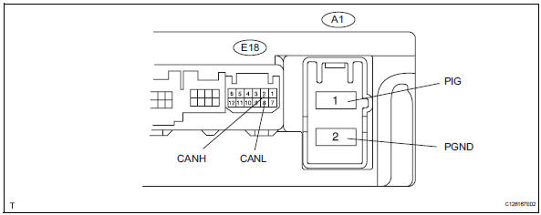
- Disconnect the a1 and e18 ecu connectors.
- Measure the resistance of the wire harness side connectors.
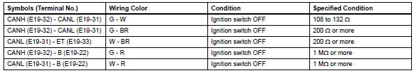
- Check combination meter ecu
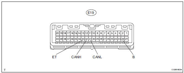
- Disconnect the e19 ecu connector.
- Measure the resistance of the wire harness side connector.
- Check instrument panel junction block (main body ecu)
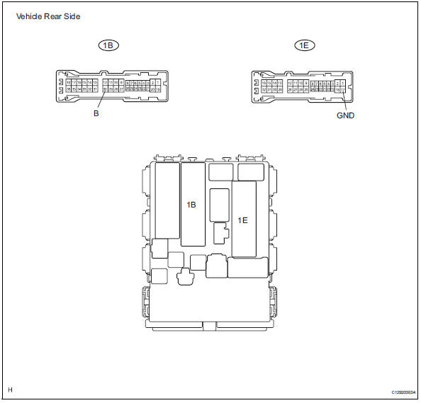
- Disconnect the 1b and 1e junction block connectors.
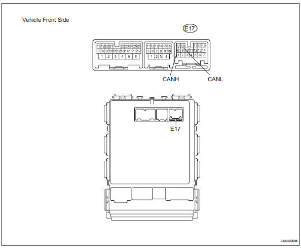
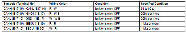
- Disconnect the e17 ecu connector.
- Measure the resistance of the wire harness side connectors.
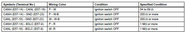
- Check 4wd control ecu (for 4wd)
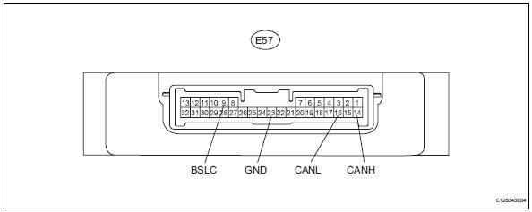
- Disconnect the e57 ecu connector.
- Measure the resistance of the wire harness side connector.
 Terminals of ecu (2005/11-2006/01)
Notice:
Turn the ignition switch off before measuring the
resistances of the main wire and the branch wire.
After the ignition switch is turned off, check that the
key reminder warning syste ...
 Diagnosis system
Bus check
Select "bus check" from the "obd / mobd
menu" screen.
Hint:
The ecus and sensors that are properly connected
to the can communication system can be di ...
Other materials:
Initialization
Initialize sliding roof drive gear subassembly
Notice:
When replacing the sliding roof drive gear, the
sliding roof drive gear requires initialization. If a
reset is not executed, the following functions do not
operate: auto operation and key off operation.
Turn the ignition switch on. ...
Front brake
Components
Removal
Hint:
Use the same procedures for the lh side and rh side.
The procedures listed below are for the lh side.
Remove front wheel
Drain brake fluid
Notice:
Wash off brake fluid immediately if it comes in
contact with any painted surface.
Disconnec ...
Basic inspection
When measuring resistance of
electronic parts
Unless otherwise stated, all resistance
measurements should be made at an ambient
temperature of 20°c (68°f). Resistance
measurements may be inaccurate if measured
at high temperatures, i.E. Immediately after the
vehicle has been r ...
