Toyota RAV4 (XA40) 2013-2018 Service Manual: Disassembly
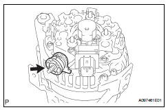
- Remove generator pulley with clutch
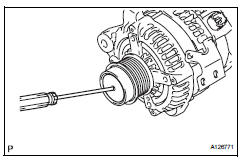
- Remove the cap from the pulley.
- Using a screwdriver, puncture the center of the cap and pry it off.
Notice:
Do not reuse the cap.
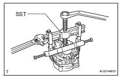
- Install sst to the pulley and vise as shown in the illustration.
Sst 09820-63020
- Mount sst (a) in a vise.
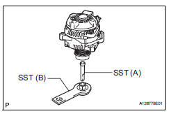
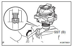
- Turn sst (b) clockwise to loosen the pulley.
- Remove the pulley.
- Remove generator brush holder assembly
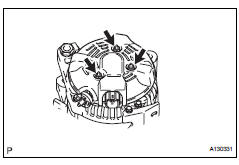
- Remove the 3 nuts and generator rear end cover.
- Remove the terminal insulator.
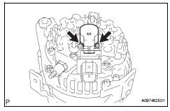
- Remove the 2 screws and generator brush holder.
- Remove generator rotor assembly
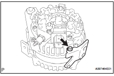
- Remove the bolt and cord clip.
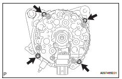
- Remove the 4 bolts.
- Using sst, remove the coil.
Sst 09950-40011 (09951-04020, 09952-04010, 09953-04020, 09954-04010, 09955-04071, 09957-04010)
- Remove the washer.
- Remove the generator rotor.
 Removal
Disconnect cable from negative battery
terminal
Caution:
Wait at least 90 seconds after disconnecting the
cable from the negative (-) battery terminal to
prevent airbag and seat belt preten ...
 Inspection
Inspect generator brush holder assembly
Using a vernier caliper, measure the brush length.
Standard length:
9.5 To 11.5 Mm (0.374 To 0.453 In.)
Minimum length:
4.5 Mm (0.177 In.)
If th ...
Other materials:
Diagnosis system
Check dlc3
Check the dlc3:
the power steering ecu uses can (iso11898-1)
and iso9141-2 for communication protocol. The
terminal arrangement of the dlc3 complies with
sae j1962 and matches the iso9141-2 format.
Notice:
*: Before measuring the resistance, leave the
vehicle ...
Do-it-yourself service precautions
If you perform maintenance
by yourself, be sure to follow
the correct procedure
as given in these sections.
Maintenance
WARNING
The engine compartment contains
many mechanisms and fluids that
may move suddenly, become hot,
or become electrically energized.
To avoid death or serious injury,
obser ...
Utility vehicle
precautions
This vehicle belongs to the utility vehicle class, which has
higher ground clearance and narrower tread in relation to the
height of its center of gravity to make it capable of performing in
a wide variety of off-road applications.
Utility vehicle feature
Specific design characteristics give ...
