Toyota RAV4 (XA40) 2013-2018 Service Manual: How to proceed with troubleshooting
Notice:
- Dtcs for the can communication system are as follows: u0073, u0100, u0105, u0121, u0122, u0123, u0124, u0126, u0129, c1280, c1296, c1297, and b1499.
- Refer to the troubleshooting procedures of each system if dtcs regarding the can communication system are not output.
- Turn the ignition switch off before measuring the resistances of the main wire and the branch wire.
- After the ignition switch is turned off, check that the key reminder warning system and light reminder warning system are not in operation.
- Before measuring the resistance, leave the vehicle for at least 1 minute and do not operate the ignition switch, any switches or doors. If doors need to be opened in order to check connectors, open the doors and leave them open.
Hint:
- *: Use the intelligent tester (with can vim).
- Operating the ignition switch, any switches or any doors triggers related ecu and sensor communication with the can, which causes resistance variation.
- Vehicle brought to workshop

- Inspect battery voltage
Standard voltage:: 11 to 14 v
If the voltage is below 11 v, recharge or replace the battery before proceeding.

- Check can bus line
- Check the can bus line (see page ca-75).

- Check installed systems (ecu and sensor) that use can communication

- Check and clear dtc*

- Check intelligent tester via can vim*
- Select "communication bus check" (see page ca- 34).
Notice:
- The systems (ecus and sensors) that use can communication vary depending on the vehicle and option settings. Check which systems (ecus and sensors) are installed on the vehicle (see page ca-34).
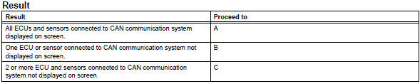
- Non-installed ecus or sensors are not displayed. Do not mistake them for being in communication stop mode
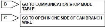
- If 2 or more ecus or sensors are not displayed on the intelligent tester, perform troubleshooting for open circuits in one side of the can branch line for each undisplayed ecu or sensor.

- Dtc combination table
- Confirm the trouble according to the combination of output dtcs regarding the can communication system.
Hint:
Previous can communication system dtcs may be the cause if can communication system dtcs are output and all ecus and sensors connected to the can communication system are displayed on the intelligent tester "communication bus check" screen.
- Check the dtc combination table (see page ca-34).

- Circuit inspection

- Identify problem

- Repair or replace

- Confirmation test

End
 System description
Brief description
The can (controller area network) is a serial data
communication system for real time application. It is
a vehicle multiplex communication system which
has a high comm ...
 Problem symptoms table
(2005/11-2006/01)
(2006/01- )
Hint:
*: For 4wd ...
Other materials:
Dtc check / clear
Check dtc
When using intelligent tester:
Connect the intelligent tester (with can vim) to
the dlc3.
Turn the ignition switch on and press the
intelligent tester main switch on.
Read the dtcs by following the prompts on the
intelligent tester.
Hint:
Refer to the intel ...
Driver side - side airbag sensor circuit malfunction
Description
The side airbag sensor lh consists of part including the diagnostic circuit
and the lateral deceleration
sensor.
When the center airbag sensor receives signals from the lateral deceleration
sensor, it determines
whether or not the srs should be activated.
Dtc b1620/21 is ...
Front axle hub bolt
Components
Replacement
Hint
Use the same procedures for the rh side and lh side.
The procedures listed below are the lh side.
Remove front wheel
Remove front disc brake cylinder
assembly lh (see page br-40)
Remove front disc (see page br-42)
Remove front axle hub bolt
...
