Toyota RAV4 (XA40) 2013-2018 Service Manual: Ignition coil
Components
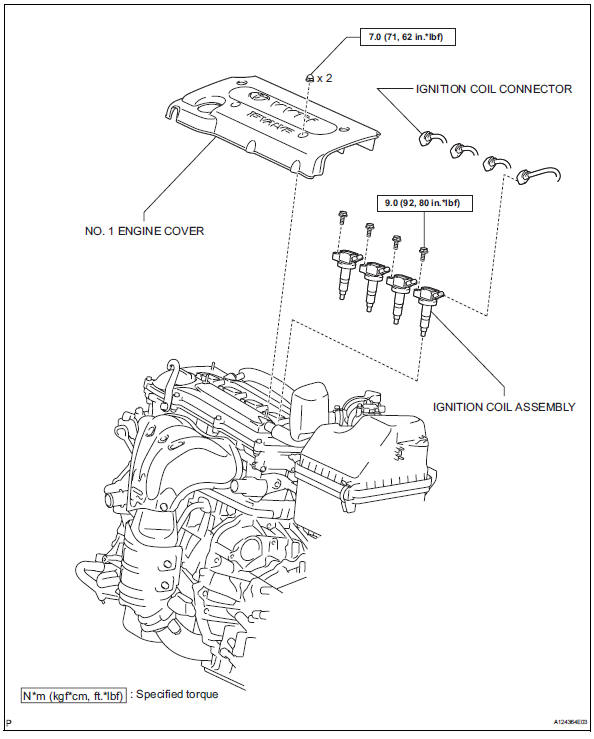
Removal
- Disconnect cable from negative battery terminal
Caution:
Wait at least 90 seconds after disconnecting the cable from the negative (-) battery terminal to prevent airbag and seat belt pretensioner activation.
- Remove no. 1 Engine cover (see page es-410)
- Remove ignition coil assembly
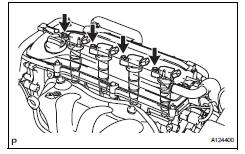
- Disconnect the 4 ignition coil connectors.
- Remove the 4 bolts and 4 ignition coils.
Installation
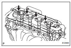
- Install ignition coil assembly
- Install the 4 ignition coils with the 4 bolts.
Torque: 9.0 N*m (92 kgf*cm, 80 in.*Lbf)
- Connect the 4 ignition coil connectors.
- Install no. 1 Engine cover (see page es-414)
- Connect cable to negative battery terminal
 On-vehicle inspection
Check ignition coil assembly and perform spark test
Notice:
in this section, the terms "cold" and "hot" refer to
the temperature of the coils. "Cold" means
appro ...
 Starting system
Parts location
System diagram
The starting system rotates the starter motor according to the
signals from the ignition switch and pnp switch.
...
Other materials:
Windshield wipers and
washer
Operating the lever can
switch between automatic
operation and manual operation,
or can use the
washer.
NOTICE
â– When the windshield is dry
Do not use the wipers, as they
may damage the windshield.
Operating the wiper lever
Operating the lever operates
the wipers or washer as follows:
Intermittent ...
Parts location
System diagram
The configuration of the electronic control system in the
u140f automatic transaxle is as shown in the following chart.
System description
System description
The electronic controlled automatic transaxle
(ect) is an automatic transaxle that elect ...
Shifting the shift lever
Vehicles without a smart key system
While the engine switch is in the
“on” position, move the shift
lever with the brake pedal depressed.
When shifting the shift lever between p and d, make sure that the
vehicle is completely stopped.
Vehicles with a smart key system
While the en ...
