Toyota RAV4 (XA40) 2013-2018 Service Manual: On-vehicle inspection
- Check ignition coil assembly and perform spark test
Notice:
in this section, the terms "cold" and "hot" refer to the temperature of the coils. "Cold" means approximately -10 to 50°c (14 to 122°f). "Hot" means approximately 50 to 100°c (122 to 212°f).
- Check the dtcs.
Notice:
If a dtc is present, perform troubleshooting in accordance with the procedure for that dtc.
- Check that sparks occur.
- Remove the no. 1 Engine cover.
- Remove the bolt and ignition coil.
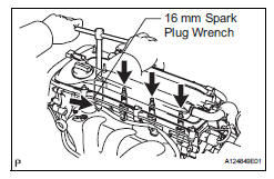
- Using a 16 mm spark plug wrench, remove the spark plug.
- Disconnect the 4 fuel injector connectors.
- Install the spark plug into the ignition coil, and then connect the ignition coil connectors.
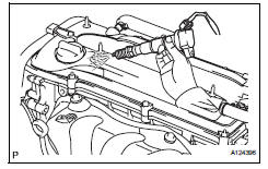
- Ground the spark plug.
- Check that sparks occur at the spark plug while the engine is being cranked.
Notice:
- Be sure to ground the spark plugs when checking them.
- If the ignition coil has been struck or dropped, replace it.
- Do not crank the engine for more than 2 seconds.
If sparks do not occur, perform the spark test.
- Using a 16 mm plug wrench, install the spark plug.
Torque: 25 n*m (254 kgf*cm, 18 ft.*Lbf)
- Install the ignition coil with the bolt.
Torque: 9.0 N*m (92 kgf*cm, 80 in.*Lbf)
- Connect the 4 fuel injector connectors.
- Install the no. 1 Engine cover.
- Spark test flow chart.
- Check that the ignition coil connector is securely connected.
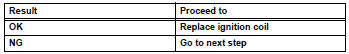
Result 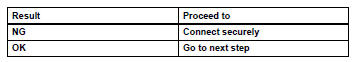
- Perform the spark test on each ignition coil.
1. Replace the ignition coil with a normal one.
2. Perform the spark test again.
Result
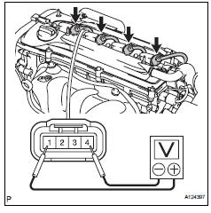
- Check the power supply to the ignition coil.
1. Disconnect the ignition coil connector.
2. Turn the ignition switch on.
3. Measure the voltage of the wire harness side connector.
Standard voltage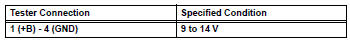
Result 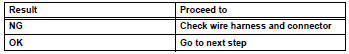
- Check the resistance of the camshaft position sensor.
Standard resistance 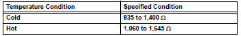
Result 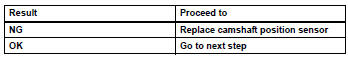
- Check the resistance of the crankshaft position sensor.
Standard resistance 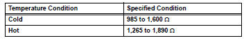
Result 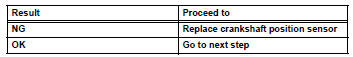
- Check the igt signal from the ecm.
Result 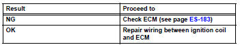
- Check spark plug
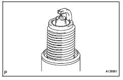
- Check the electrode.
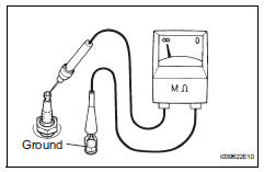
- Using a megohmmeter, measure the insulation resistance
Standard insulation resistance:
10 m or more
Hint:
- If a megohmmeter is not available, perform the following simple inspection instead.
- If the result is 10 mù or less, clean the plug and measure the resistance again.
- Alternative inspection method:
- Quickly accelerate the engine to 4,000 rpm 5 times.
- Remove the spark plug.
- Visually check the spark plug.
If the electrode is dry, the spark plug is functioning properly. If the electrode is damp, proceed to the next step.
- Check the spark plug for any damage on its threads and insulator.
If there is damage, replace the spark plug.
Recommended spark plug 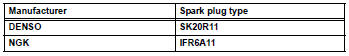
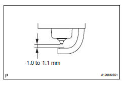
- Check the spark plug electrode gap.
Maximum electrode gap for used spark plug: 1.3 Mm (0.051 In.)
If the gap is greater than the maximum, replace the spark plug.
Electrode gap for new spark plug: 1.0 To 1.1 Mm (0.039 To 0.043 In.)
- Clean the spark plugs.
If the electrode has traces of wet carbon, clean the electrode with a spark plug cleaner and then dry it.
Standard air pressure: 588 kpa (6 kgf*cm2, 85 psi)
Standard duration: 20 seconds or less
Hint:
Only use the spark plug cleaner when the electrode is free of oil. If the electrode has traces of oil, use gasoline to clean off the oil before using the spark plug cleaner.
 System diagram
...
 Ignition coil
Components
Removal
Disconnect cable from negative battery terminal
Caution:
Wait at least 90 seconds after disconnecting the
cable from the negative (-) battery terminal to
prevent airb ...
Other materials:
Tire information
Typical tire symbols
Full-size tire
Compact spare tire
Tire size
DOT and Tire Identification Number (TIN)
Location of treadwear indicators
Tire ply composition and materials
Plies are layers of rubber-coated parallel cords. Cords are the strands
which form the plies in a tire.
Radial tir ...
Problem symptoms table (2006/01- )
Hint:
Use the table below to help determine the cause of the
problem symptom. The potential causes of the symptoms
are listed in order of probability in the "suspected area"
column of the table. Check each symptom by checking the
suspected areas in the order they are listed. R ...
Deterioration of battery
Description
The ecm determines the battery power according to the voltage of the batt
terminal while the engine is
running (not cranking).
Inspection procedure
Inspect battery
Inspect the battery specific gravity.
Check the specific gravity of each cell.
Standard gravity: ...
