Toyota RAV4 (XA40) 2013-2018 Service Manual: Engine control system malfunction
![]()
Description
If a malfunction in the engine control system is detected, the operations of vsc and trc are prohibited by the fail-safe function. When the signals from the engine are input normally, the fail-safe is canceled and the dtc is not stored.

Inspection procedure
- Check harness and connector (momentary interruption)
- Using the data list of the intelligent tester, check for any momentary interruption in the wire harness corresponding to the dtc (see page bc-23).
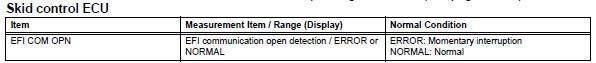
Ok: there are no momentary interruptions.
Hint:
Perform the above inspection before removing the sensor and connector.

- Check dtc for engine control system
- Clear the dtc (engine control system).
- Check the dtc (engine control system).
Result 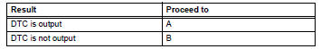

Repair engine control system
- Repair or replace harness and connector (ecm - skid control ecu)

- Reconfirm dtc
- Clear the dtc (see page bc-47).
- Perform a road test.
- Check if the same dtc is recorded (see page bc-47).
Result 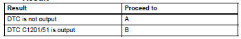

End
 Open in abs solenoid relay circuit
Description
The solenoid relay supplies power to the abs solenoid and trc solenoid.
After the ignition switch is turned on, the vehicle speed has reached 6 km/h (4
mph) and the solenoid is
...
 Ecm communication circuit malfunction
Description
The circuit is used to send trc and vsc control information from the skid
control ecu to the ecm, and
engine control information from the ecm to the skid control ecu.
Inspecti ...
Other materials:
Closing the fuel tank cap
After refueling, turn the fuel tank
cap until you hear a click. Once
the cap is released, it will turn
slightly in the opposite direction.
Caution
When replacing the fuel tank cap
Do not use anything but a genuine toyota fuel tank cap designed for
your
vehicle. Doing so may cause a fire ...
Sruepsptrleaminetnstal restraint system center airbag sensor assembly
Components
On-vehicle inspection
Check center airbag sensor assembly
(vehicle not involved in collision and
airbag not deployed)
Perform a diagnostic system check (see page rs-
49).
Check center airbag sensor assembly
(vehicle involved in collision and airbag
not deplo ...
Reassembly
V
Attach the 7 outside moulding retainers to install the
extension.
Install front bumper extension rh (for wide
body)
Hint:
Use the same procedures described for the lh side.
Install front bumper hole cover lh (w/o fog
light)
Install the bumper hole cover with ...
