Toyota RAV4 (XA40) 2013-2018 Service Manual: Ecm communication circuit malfunction
![]()
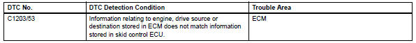
Description
The circuit is used to send trc and vsc control information from the skid control ecu to the ecm, and engine control information from the ecm to the skid control ecu.
Inspection procedure
Hint:
Check that the part numbers of the installed ecm and skid control ecu are correct before performing the following procedure.
- Reconfirm dtc
- Clear the dtc (see page bc-47).
- Start the engine.
- Check if the same dtc is output (see page bc-47).
Result 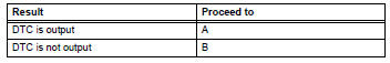


Replace ecm
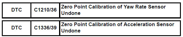
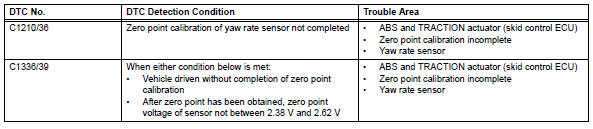
Zero point calibration
Description
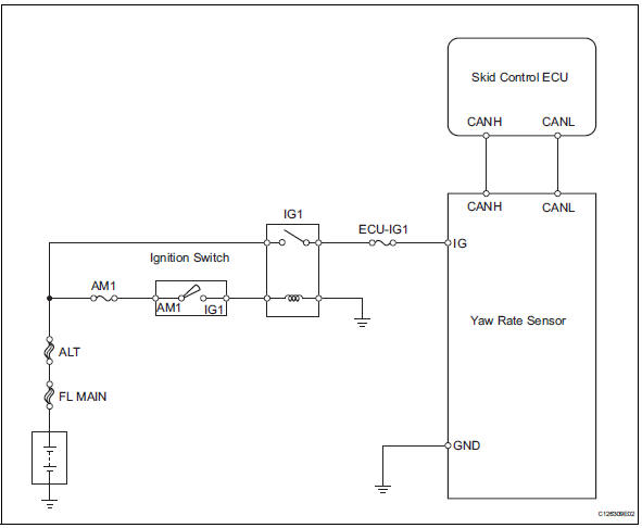
The abs and traction actuator (skid control ecu) receives signals from the yaw rate and deceleration sensor via the can communication system. The yaw rate sensor has a built-in deceleration sensor and detects the vehicle's condition using 2 circuits (gl1, gl2). If there are problems in the bus lines between the yaw rate and deceleration sensor and the can communication system, dtcs u0123/62 (yaw rate sensor communication trouble) and u0124/95 (deceleration sensor communication trouble) are output.
The dtcs are also output when the calibration has not been completed.
Wiring diagram
Inspection procedure
Notice:
When replacing the abs and traction actuator, perform the zero point calibration (see page bc- 24).
Hint
When dtc u0123/62, u0124/95 or u0126/63 is output together with dtc c1210/36 or c1336/39, inspect and repair trouble areas indicated by dtc u0123/62, u0124/95 or u0126/63 first.
- Check yaw rate sensor installation
- Check that the yaw rate sensor has been installed properly (see page bc-211).
Ok: the sensor is tightened to the specified torque.
The sensor is not tilted.

- Perform zero point calibration of yaw rate sensor
- Perform zero point calibration of the yaw rate and deceleration sensor (see page bc-24).

- Reconfirm dtc
- Clear the dtc(s) (see page bc-47).
- Start the engine.
- Drive the vehicle and turn the steering wheel to the right and left at a speed of 45 km/h (28 mph) or more.
- Check if the same dtc(s) is recorded (see page bc- 47).
Result 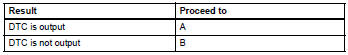
Hint:
- The dtc(s) is set if the zero point calibration has not been completed successfully.
- End the procedure when the same dtc(s) is not set after completion of the zero point calibration.

Replace abs and traction actuator assembly
 Engine control system malfunction
Description
If a malfunction in the engine control system is detected, the operations of
vsc and trc are prohibited
by the fail-safe function. When the signals from the engine are input normal ...
 Abs control system malfunction
Description
This dtc is output when the vsc system detects a malfunction in the abs
system.
Inspection procedure
Check dtc for abs system
Clear the dtc (see page bc-47).
Turn t ...
Other materials:
Voice settings
This screen is used for setting the voice command guidance
system.
Adjust the voice guidance volume
setting.
Set the voice recognition
prompts “high”, “low” or “off”.
Train voice recognition
Set the voice prompt interrupt
on/off.
Voice recognition tutorial
To re ...
Front occupant classification sensor lh collision detection
Description
Dtc b1785 is output when the occupant classification ecu receives a collision
detection signal sent by
the front occupant classification sensor lh when an accident occurs.
Dtc b1785 is also output when the front seat rh is subjected to a strong impact,
even if an actual
acc ...
Terminals of ecu
Check power steering ecu
Hint:
Measurements cannot be performed on the c connector
side of the power steering ecu.
Measure the voltage and resistance of the
connectors.
If the result is not as specified, the ecu may have a
malfunction. ...
