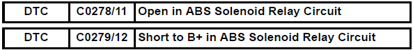
Toyota RAV4 (XA40) 2013-2018 Service Manual: Open in abs solenoid relay circuit
Description
The solenoid relay supplies power to the abs solenoid and trc solenoid.
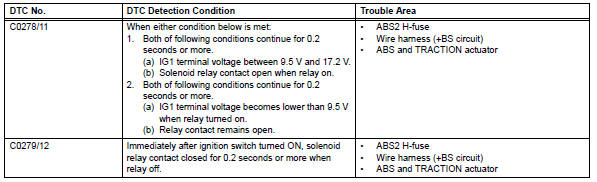
After the ignition switch is turned on, the vehicle speed has reached 6 km/h (4 mph) and the solenoid is determined to be normal by the initial check self-diagnosis, the relay switches on. If any open or short circuits are detected, the relay switches off.
These dtcs may be set if the voltage supply to the solenoid relay (+bs) falls below the dtc detection threshold due to the battery or alternator outputs being insufficient.
Hint:
Dtcs c0278/11 and c0279/12: the skid control ecu begins to detect these dtcs when the vehicle speed exceeds 6 km/h (4 mph).
Wiring diagram
Refer to dtc c0273/13, c0274/14, c1361/91 (see page bc-79).
Inspection procedure
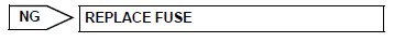
- Inspect fuses (abs2)
- Remove the abs2 h-fuse from the engine room no. 1 Relay block.
- Measure the resistance of the fuse.
Standard resistance:
below 1 

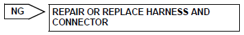
- Check wire harness (skid control ecu - battery and body ground)
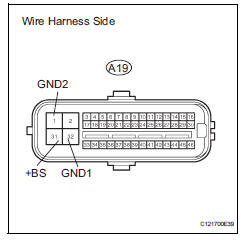
- Disconnect the a19 ecu connector.
- Measure the voltage of the wire harness side connector.
Standard voltage 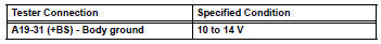
- Measure the resistance of the wire harness side connector.
Standard resistance 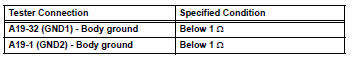

- Reconfirm dtc
- Clear the dtcs (see page bc-47).
- Start the engine.
- Drive the vehicle at 6 km/h (4 mph) or more to activate the initial check.
- Check if the same dtcs is output (see page bc-47).
Result 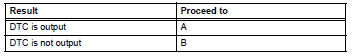

Replace abs and traction actuator assembly
 Solenoid circuit
Description
This solenoid is turned on in accordance with signals from the skid control
ecu and controls the pressure
on the wheel cylinders to control the braking force.
The solenoid and s ...
 Engine control system malfunction
Description
If a malfunction in the engine control system is detected, the operations of
vsc and trc are prohibited
by the fail-safe function. When the signals from the engine are input normal ...
Other materials:
Cleaning and protecting the vehicle interior
Perform cleaning in a manner
appropriate to each
component and its material.
Protecting the vehicle
interior
Remove dirt and dust using a
vacuum cleaner. Wipe dirty
surfaces with a cloth dampened
with lukewarm water.
If dirt cannot be removed,
wipe it off with a soft cloth
dampened with neut ...
Starting system
Parts location
System diagram
The starting system rotates the starter motor according to the
signals from the ignition switch and pnp switch.
...
Removal
Hint:
Use the same procedures for the rh side and lh side.
The procedures listed below are for the lh side.
Caution:
Be sure to read the precautionary notices concerning the
srs airbag system before servicing it (see page rs-1).
Disconnect cable from negative battery terminal
Cauti ...
