Toyota RAV4 (XA40) 2013-2018 Service Manual: Installation
Caution:
Be sure to read the precautionary notices concerning the srs airbag system before servicing it (see page rs-1).
- Install steering pad assembly
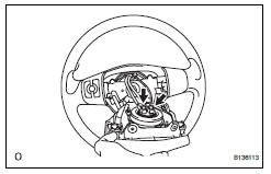
- Support the steering pad with one hand as shown in the illustration.
- Connect the 2 airbag connectors.
Notice:
When handling the airbag connector, do not damage the airbag wire harness.
- Connect the horn connector.
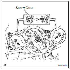
- Install the steering pad after confirming that the circumference grooves of the screws are caught on the screw case.
- Using a t30 "torx" driver, install the 2 screws.
Torque: 8.8 N*m (90 kgf*cm, 78 in.*Lbf)
- Connect cable to negative battery terminal
- Inspect steering pad assembly
- Check for cuts, cracks or discoloration on the steering pad outer surface and in the grooved portion.
- Check that the horn sounds.
- Check srs warning light
- Check the srs warning light (see page rs-34).
 Removal
Caution:
Be sure to read the precautionary notices concerning the
srs airbag system before servicing it (see page rs-1).
Disconnect cable from negative battery
terminal
Caution:
Wait at le ...
 Disposal
Hint:
When scrapping a vehicle equipped with an srs or disposing
of the steering pad, be sure to deploy the airbag first in
accordance with the procedure described below. If any
abnormality occurs ...
Other materials:
Lost communication with front satellite sensor bus lh
Description
The front airbag sensor lh consists of the diagnostic circuit and the frontal
deceleration sensor.
If the center airbag sensor receives signals from the frontal deceleration
sensor, it determines whether or
not the srs should be activated.
Dtc b1607/84, b1608/84, b1617/84 ...
Setup menu
You can adjust the audio system to your desired settings.
Display “setup” screen
Press the “setup” button to display the “setup” screen.
Select to adjust the settings for
operation sounds, screen animation,
etc.
Select to display the voice settings
screen.
Select to adjus ...
Evaporator temperature sensor circuit
Description
The no. 1 Cooler thermistor (evaporator temperature sensor) is installed on
the evaporator in the air
conditioning unit to detect the temperature of the cooled air that has passed
through the evaporator and to
control the air conditioner. It sends signals to the air conditioni ...
