Toyota RAV4 (XA40) 2013-2018 Service Manual: Installation
Hint:
- Use the same procedures for the rh side and lh side.
- The procedures listed below are for the lh side.
- Install rear stabilizer bush
- Install the 2 bushes.
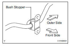
Hint:
- Install each bush to the outer side of the bush stopper on each stabilizer bar.
- Install each bush with its slit facing the vehicle front side.
- Install rear stabilizer bar
- Install the stabilizer bar to the vehicle.
Notice:
When installing the stabilizer bar, make sure not to damage the sensor wires, brake hoses, etc.
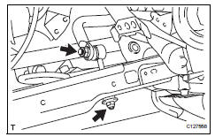
- Install rear no. 1 Stabilizer bar bracket
- Install the bracket with the 2 nuts.
Torque: 60 n*m (612 kgf*cm, 44 ft.*Lbf)
- Install rear coil spring insulator lower lh (see page sp-34)
- Install rear coil spring lh (see page sp-34)
- Install rear coil spring insulator upper lh (see page sp-34)
- Install rear coil spring insulator lower rh
Hint
Use the same procedures described for the lh side.
- Install rear co3h
Hint:
Use the same procedures described for the lh side.
- Install rear coil spring insulator upper rh
Hint:
Use the same procedures described for the lh side.
- Temporarily install rear no. 2 Suspension arm assembly lh (see page sp-46)
- Temporarily install rear no. 2 Suspension arm assembly rh
Hint:
Use the same procedures described for the lh side.
- Install rear stabilizer link assembly lh
- Install the stabilizer link with the 2 nuts.
Torque: 74 n*m (755 kgf*cm, 55 ft.*Lbf) for stabilizer bar
30 N*m (306 kgf*cm, 22 ft.*Lbf) for suspension no. 2 Arm
- Install rear stabilizer link assembly rh
Hint:
Use the same procedures described for the lh side.
- Install rear wheel
Torque: 103 n*m (1,050 kgf*cm, 76 ft.*Lbf)
- Stabilize suspension (see page sp-37)
- Tighten rear no. 2 Suspension arm assembly lh (see page sp-46)
- Tighten rear no. 2 Suspension arm assembly rh
Hint:
Use the same procedures described for the lh side.
- Inspect and adjust rear wheel alignment
- Inspect and adjust the rear wheel alignment (see page sp-7).
- Check speed sensor signal
- Check the speed sensor signal (see page bc-44).
 Inspection
Inspect rear stabilizer link assembly lh
As shown in the illustration, move the ball joint stud
back and forth 5 times before installing the nut.
Using a torque wrench, turn the nut c ...
 Drive shaft
...
Other materials:
How to proceed with troubleshooting
Hint:
Use these procedures to troubleshoot the key reminder
warning system.
*: Use the intelligent tester.
Vehicle brought to workshop
Inspect battery voltage
Standard voltage:
11 to 14 v
Hint:
If the voltage is below 11 v, recharge or replace the battery
before proceedi ...
Removal
Table of bolt, screw and nut
Hint:
All bolts, screws and nuts relevant to installing and
removing the instrument panel are shown along with
their alphabet codes in the table below.
Disconnect cable from negative battery
terminal
Caution:
Wait at least 90 seconds after disconne ...
Lost communication with front passenger side - side airbag sensor assembly
Description
The side airbag sensor rh consists of parts including the diagnostic circuit
and the lateral deceleration
sensor.
When the center airbag sensor receives signals from the lateral deceleration
sensor, it determines
whether or not the srs should be activated.
Dtc b1627/82 i ...
