Toyota RAV4 (XA40) 2013-2018 Service Manual: Installation (2005/11-2006/01)
- Install abs and traction actuator assembly with bracket
Notice:
Do not remove the hole plug before connecting the brake tube. New actuators are filled with brake fluid.
- Install the actuator with bracket with the 3 nuts.
Torque: 19 n*m (194 kgf*cm, 14 ft.*Lbf)
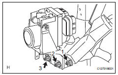
Hint:
The nuts should be tightened in order from 1 to 3 as shown in the illustration.
Notice:
Be careful not to damage the brake tubes.
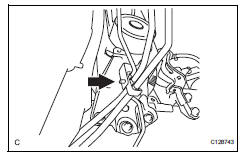
- Connect the brake tube clamp to the bracket.
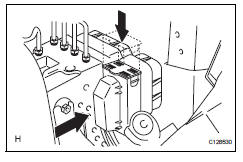
- Connect the connector and push the lock lever downward.
- Connect brake lines
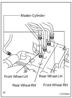
- Using sst, connect the 6 brake lines to the correct locations on the actuator, as shown in the illustration.
Sst 09023-00101
Torque: 15.2 N*m (155 kgf*cm, 11 ft.*Lbf) without sst
14 N*m (144 kgf*cm, 10 ft.*Lbf) with sst
Hint:
Use a torque wrench with a fulcrum length of 30 cm (11.81 In.).
- Fill reservoir with brake fluid (see page br- 6)
- Bleed air from brake master cylinder (see page br-7)
- Bleed air from brake line (see page br-7)
- Bleed air from abs and traction actuator assembly (see page br-8)
- Check brake fluid level in reservoir (see page br-6)
- Check for brake fluid leakage
- Install air cleaner case sub-assembly
- Install the air cleaner case (see page em-105).
Hint:
Refer to the procedures from the installation of the air cleaner case up until the installation of the purge vsv.
- Connect cable to negative battery terminal
- Check abs and traction actuator assembly with intelligent tester
- Check the abs and traction actuator with the intelligent tester (see page bc-180).
 Removal (2006/01- )
Disconnect cable from negative battery
terminal
Caution:
Wait at least 90 seconds after disconnecting the
cable from the negative (-) battery terminal to
prevent airbag and seat belt preten ...
 Front speed sensor
Components
Removal
Hint:
Use the same procedures for the lh side and rh side.
The procedures listed below are for the lh side.
Disconnect cable from negative battery
terminal
Ca ...
Other materials:
Differential oil
On-vehicle inspection
Check differential oil
Stop the vehicle on a level surface.
Using a 10 mm socket hexagon wrench, remove the
rear differential filler plug and gasket.
Check that the oil level is between 0 to 5 mm (0 to
0.20 In.) From the bottom lip of the different ...
Hitch
Trailer hitch assemblies have different weight capacities. Toyota recommends
the use of toyota hitch/bracket for your vehicle. For details,
contact your toyota dealer.
If you wish to install a trailer hitch, contact your toyota dealer.
Use only a hitch that conforms to the gross trailer weig ...
Using the steering
wheel switches
The steering wheel switches can be used to operate a connected
cellular phone.
Operating a telephone using the steering wheel switches
Volume switch
Increase/decrease the volume
Press and hold:
continuously increase/
decrease the volume
Enter switch
Select an item
...
