Toyota RAV4 (XA40) 2013-2018 Service Manual: Front speed sensor
Components
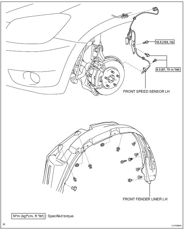
Removal
Hint:
- Use the same procedures for the lh side and rh side.
- The procedures listed below are for the lh side.
- Disconnect cable from negative battery terminal
Caution:
Wait at least 90 seconds after disconnecting the cable from the negative (-) battery terminal to prevent airbag and seat belt pretensioner activation.
- Remove front wheel
- Remove front fender liner lh
- Remove front speed sensor lh
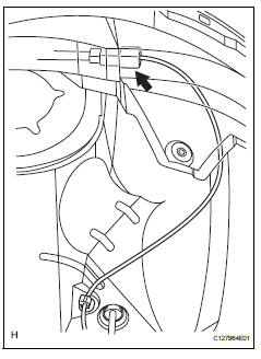
- Disconnect the sensor connector.
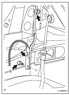
- Remove the sensor clip (labeled a), bolt (labeled b) and sensor clamp (labeled c).
- Remove the sensor clip (labeled d), bolt (labeled e) and sensor clamp (labeled f).
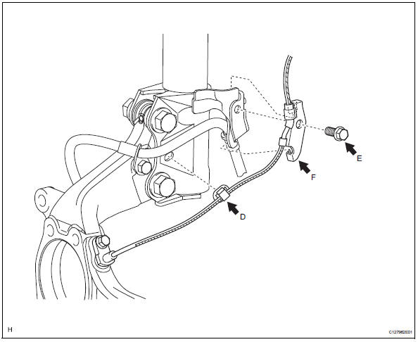
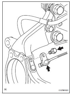
- Remove the bolt and sensor body from the knuckle.
Notice:
Keep the sensor tip and sensor installation hole free from foreign matter.
 Installation (2005/11-2006/01)
Install abs and traction actuator assembly with bracket
Notice:
Do not remove the hole plug before connecting the
brake tube. New actuators are filled with brake fluid.
Install the actuato ...
 Installation (2006/01- )
Install abs and traction actuator assembly with bracket
Notice:
do not remove the hole plug before connecting the
brake tube. new actuators are filled with brake fluid.
Install the actuato ...
Other materials:
Bus ic communication malfunction
Description
The air conditioning harness connects the air conditioning amplifier and the
servos. The air conditioning
amplifier supplies power and sends operation instructions to each servo through
the air conditioning
harness. Each servo sends damper position information to the air condi ...
Rear door courtesy switch
Components
Removal
Hint:
Use the same procedures for the rh and lh sides.
The procedures listed below are for the lh side.
Disconnect cable from negative battery
terminal
Caution:
Wait at least 90 seconds after disconnecting the
cable from the negative (-) battery terminal t ...
Terminals of ecm
Check ecm
Disconnect the a9 and b30 connectors.
Measure the voltage and resistance of the wire
harness side connectors.
If the result is not as specified, there may be a
malfunction on the wire harness side. ...
