Toyota RAV4 (XA40) 2013-2018 Service Manual: Installation
Hint:
- Use the same procedures for the lh side and rh side.
- The procedures listed below are for the lh side.
- Install speed sensor front lh
Notice:
To prevent interference with other parts, do not twist the sensor wire's painted line areas when installing it.
- Set the sensor body to the knuckle, and then install the sensor with the bolt.
Torque: 8.5 N*m (87 kgf*cm, 75 in.*Lbf)
Notice:
- Keep the sensor tip and sensor installation hole free from foreign matter.
- Firmly insert the sensor body into the knuckle before tightening the bolt.
- After installing the sensor to the knuckle, make sure that there is no clearance between the sensor stay and knuckle. Also make sure that no foreign matter is stuck between the parts.
- To prevent interference between the sensor and magnetic rotor, do not rotate the sensor body during or after the insertion of the sensor body to the knuckle.
- Install the sensor clamp and sensor clip as follows.
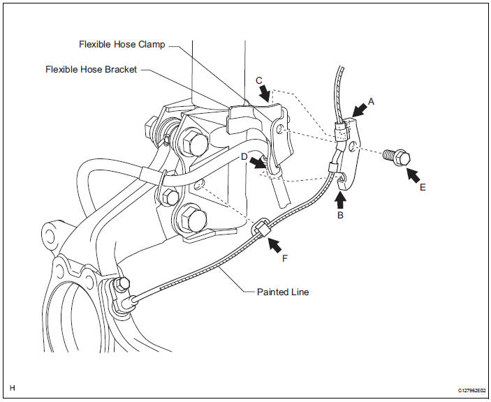
- Set the flexible hose clamp on the flexible hose bracket.
- Simultaneously perform the following: 1) hang the hook part of the sensor clamp (labeled a) on the flexible hose bracket (labeled c); and 2) insert the hook part of the sensor clamp (labeled b) into the flexible hose bracket (labeled d).
Notice:
Do not twist the sensor wire when installing the clamp.
- Tighten together the sensor clamp, flexible hose clamp and flexible hose bracket with the bolt (labeled e).
Torque: 18.5 N*m (189 kgf*cm, 14 ft.*Lbf)
- Insert the sensor clip (labeled f) into the hole on the absorber lower bracket.
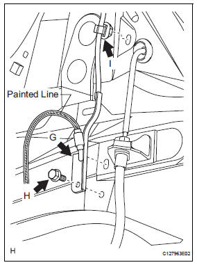
- Install the sensor clamp, and sensor clip as follows.
- Set the sensor clamp (labeled g) on the side member, and then tighten it with the bolt (labeled h).
Torque: 8.5 N*m (87 kgf*cm, 75 in.*Lbf)
Notice:
Do not twist the sensor wire when installing the clamp.
- Insert the sensor clip (labeled i) into the hole on the apron.
- Connect the sensor connector.

- Install front fender liner lh
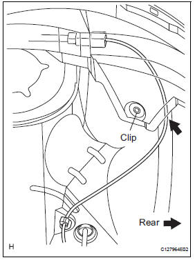
Hint:
Install the fender liner so that the sensor wire harness passes beyond the fender liner installation clip towards the rear side of the vehicle.
- Install front wheel
Torque: 103 n*m (1,050 kgf*cm, 76 ft.*Lbf)
- Connect cable to negative battery terminal
- Check abs speed sensor signal
- Check the speed sensor signal (see page bc-28).
 Installation (2006/01- )
Install abs and traction actuator assembly with bracket
Notice:
do not remove the hole plug before connecting the
brake tube. new actuators are filled with brake fluid.
Install the actuato ...
 Skid control sensor (for 2wd)
Components
Removal
Hint:
Use the same procedures for the lh side and rh side.
The procedures listed below are for the lh side.
Disconnect cable from negative battery
terminal
Ca ...
Other materials:
Data list / active test
Read data list
Hint:
Using the intelligent tester's data list allows switch,
sensor, actuator and other item values to be read without
out removing any parts. Reading the data list early in
troubleshooting is one way to save time.
Connect the intelligent tester (with can vim) to the
...
System diagram
System diagram (2005/11-2006/01)
System diagram (2006/01- )
...
When servicing active torque control 4wd vehicles
The active torque control 4wd rav4 is equipped
with the 4 wheel drive control system.
If incorrect preparations or test procedures are
used, the test will not only be unsuccessful, but may
be dangerous as well.
Caution:
Never accelerate or decelerate the vehicle
suddenly.
Obs ...
