Toyota RAV4 (XA40) 2013-2018 Service Manual: Outer rear view mirror
Components
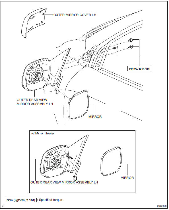
Removal
Hint:
- Use the same procedures for the lh side and rh side.
- The procedures listed below are for the lh side.
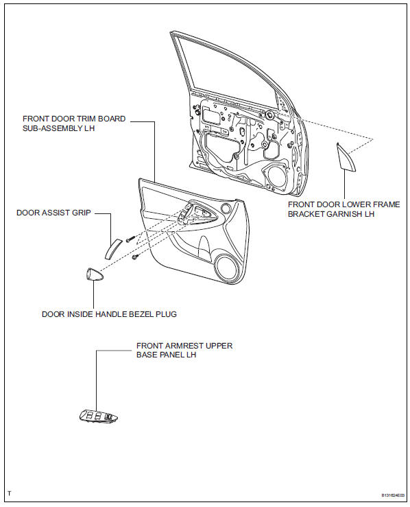
- Remove front door lower frame bracket garnish lh (see page ed-19)
- Remove front armrest upper base panel lh (see page ed-19)
- Remove front door trim board subassembly lh (see page ed-20)
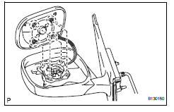
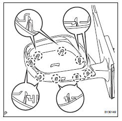
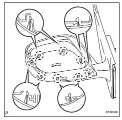
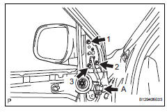
- Remove outer rear view mirror assembly lh
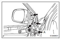
- Disconnect the mirror connector labeled a.
- Remove the 3 screws.
- Remove the outer rear view mirror.
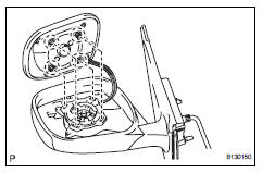
- Remove outer mirror cover lh (w/ mirror heater)
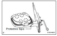
- Using a moulding remover, detach the 4 claws.
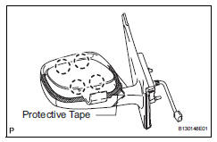
Hint:
Apply protective tape to the mirror body.
- Remove the 2 connectors and disconnect the mirror.
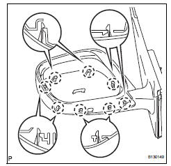
- Using a screwdriver, detach the 8 claws and remove the mirror cover.
Hint:
Tape the screwdriver tip before use.
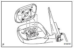
- Remove outer mirror cover lh (w/o mirror heater)
- Using a moulding remover, detach the 4 claws.
Hint:
Apply protective tape to the mirror body.
- Disconnect the mirror.
- Using a screwdriver, detach the 8 claws and remove the mirror cover.
Hint:
Tape the screwdriver tip before use.
Inspection
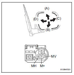
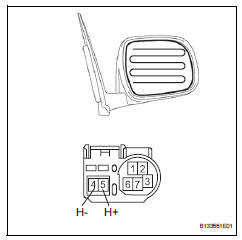
- Inspect outer rear view mirror assembly lh
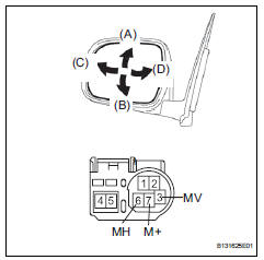
- Disconnect the mirror connector.
- Apply battery voltage and check the operation of the mirror.
Ok 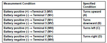
If the result is not as specified, replace the mirror assembly.
- W/ mirror heater:
Check the resistance.
- Measure the resistance between the terminals.
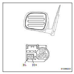
Standard resistance
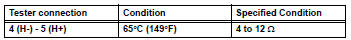
If the result is not as specified, replace the outer rear view mirror.
- Connect the cable from the negative battery (-) terminal to terminal 5 and the positive battery (+) terminal to terminal 4, then check that the mirror becomes warm.
Ok: mirror becomes warm.
Hint:
It takes a short time for the mirror to become warm.
If the result is not as specified, replace the outer rear view mirror.
- Inspect outer rear view mirror assembly rh
- Disconnect the mirror connector.
- Apply battery voltage and check the operation of the mirror.
Ok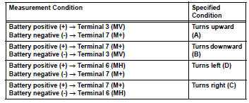
If the result is not as specified, replace the mirror assembly.
- W/ mirror heater:
Check the resistance.
- Measure the resistance between the terminals.
Standard resistance
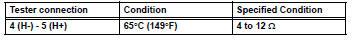
If the result is not as specified, replace the outer rear view mirror.
- Connect the cable from the negative battery (-) terminal to terminal 5 and the positive battery (+) terminal to terminal 4, then check that the mirror becomes warm.
Ok: mirror becomes warm.
Hint:
It takes a short time for the mirror to become warm.
If the result is not as specified, replace the outer rear view mirror.
Installation
- Install outer mirror cover lh
- Attach the 8 claws and install the mirror cover.
- After installing the outer mirror cover, check that there is no gap between the cover and mirror body.
Hint:
If there is a gap between the cover and body, noise will occur during driving.
- W/ mirror heater: connect the 2 connectors. Attach the 4 claws to install the mirror.
- W/o mirror heater: attach the 4 claws to install the mirror.
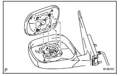
- Install outer rear view mirror assembly lh
- Pass the connector labeled a and wire harness of the mirror through the wire harness hole.
- Temporarily install the mirror by inserting the bosses on the mirror into the holes on the vehicle.
- Tighten the 3 screws in the sequence shown in the
illustration and install the mirror.
Torque: 9.0 N*m (92 kgf*cm, 80 in.*Lbf)
- Connect the connector labeled a.
- Install front door trim board subassembly lh (see page ed-33)
- Install front door lower frame bracket garnish lh (see page ed-35)
 Inner rear view mirror
Components
Removal
Remove inner rear view mirror assembly
Disengage the 2 claws and separate the inner rear
view mirror cover as shown in the illustration.
Remove the in ...
 Outer mirror switch
Inspection
Inspect outer mirror switch assembly
The l position of the left/right adjustment switch:
measure the resistance of the mirror switch.
Standard resistance (for left side)
...
Other materials:
Precaution
Tire pressure warning system precaution
When the tire pressure warning light turns on,
immediately check the tire pressure of the tire and
adjust it to the specified value. (When the tire
pressure warning light circuit is open, the tire
pressure warning light flashes for 1 minut ...
Receiver error
Description
Wiring diagram
Inspection procedure
Notice:
It is necessary to register an id code after replacing the tire pressure
warning valve abd
transmitter and/or the tire pressure warning ecu (see page tw-9).
Hint:
Set the tire pressure to the specified value.
Standard pres ...
On-vehicle inspection
Check driver side seat belt warning light
Turn the ignition switch on.
When the driver side seat belt is not fastened, check
that the combination meter's driver side seat belt
warning light starts blinking.
When the seat belt is fastened, check that the
combination meter's driver ...
