Toyota RAV4 (XA40) 2013-2018 Service Manual: Parts location
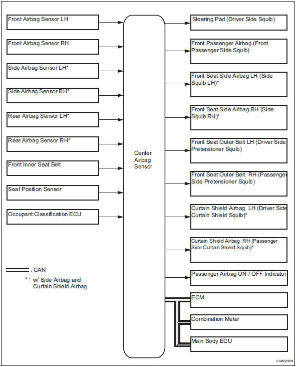
System diagram
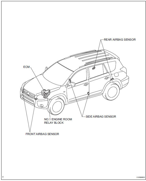
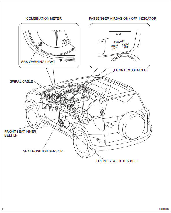
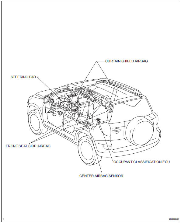
 Precaution
Caution:
The vehicle is equipped with a supplemental restraint
system (srs), which consists of a steering pad, front
passenger airbag, curtain shield airbag, front seat side
airbag, seat bel ...
 System description
General
In conjunction with an impact absorbing structure for
a frontal collision, the srs (supplemental restraint
system) driver airbag, front passenger airbag and
driver side knee air ...
Other materials:
Front occupant classification sensor lh circuit
malfunction
Description
The front occupant classification sensor lh circuit consists of the occupant
classification ecu and the
front occupant classification sensor lh.
Dtc b1780 is recorded when a malfunction is detected in the front occupant
classification sensor lh
circuit.
Wiring diagram
...
Display contents
Following information is displayed
on the multi-information
display.
Content display area (left)
Content display area (center)
Content display area (right)
Driving support system information
display area
When driving information support
system is displayed on the content
display area, the sy ...
Throttle / pedal position sensor / switch "A"
Hint:
These dtcs relate to the throttle position (tp) sensor.
Description
The tp sensor is mounted on the throttle body, and detects the opening angle
of the throttle valve. This
sensor is a non-contact type. It uses hall-effect elements in order to yield
accurate signals even in
extrem ...
