Toyota RAV4 (XA40) 2013-2018 Service Manual: Precaution
- Inspection procedure for vehicle involved in accident
- Perform the zero point calibration and sensitivity check if any of the following conditions apply.
- The occupant classification ecu is replaced.
- Accessories (seat cover etc.) Are installed.
- The front passenger seat is removed from the vehicle.
- The passenger airbag on/off indicator (off) comes on when the front passenger seat is not occupied.
- The vehicle is brought to the workshop for repair due to an accident or a collision.
Notice:
When a vehicle involved in an accident is brought into the workshop for repair, check the flatness of the floor where the front passenger seat is mounted. If the flatness is not within +- 3.0 Mm (+-0.118 In.), Adjust it to the specified range.
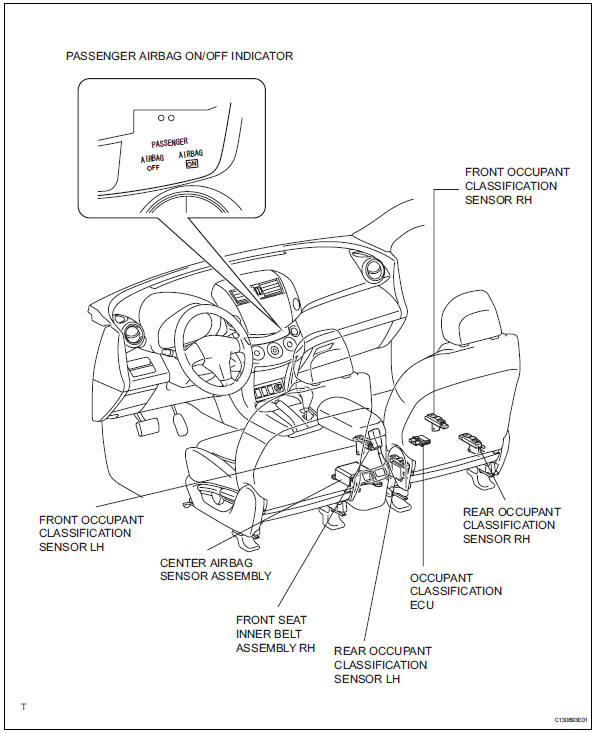
Parts location
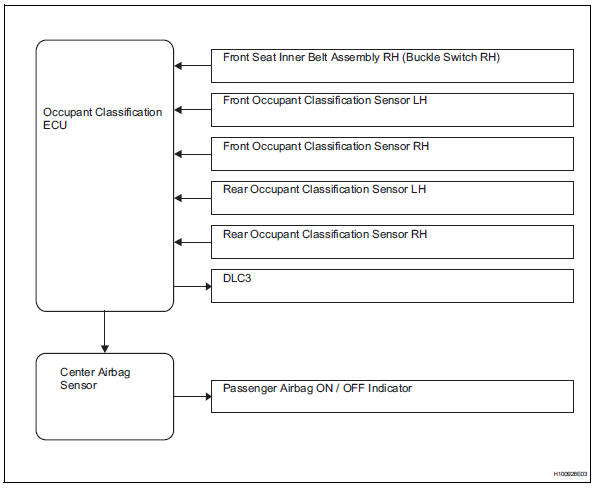
System diagram

 System description
General
The front passenger occupant classification system
judges whether the front passenger seat is occupied
or not in accordance with the seat belt buckle
status; and whether the sea ...
Other materials:
On-vehicle inspection
Check ignition coil assembly and perform spark test
Notice:
in this section, the terms "cold" and "hot" refer to
the temperature of the coils. "Cold" means
approximately -10 to 50°c (14 to 122°f). "Hot" means
approximately 50 to 100°c (122 to 212 ...
Fog light switch
The fog lights secure excellent visibility in difficult driving
conditions,
such as in rain and fog.
(U.S.A.) Or (canada)
turns the fog lights off
Turns the fog lights on
Fog lights can be used when
The headlights are on in low beam. ...
Rear seats
Reclining adjustments and
folding the seatbacks can
be done with lever operation.
Adjustment procedure
Pull the seatback angle adjustment
lever A, and adjust the
seatback angle.
WARNING
â– When operating the seatback
Observe the following precautions.
Failure to do so may cause death
or serious in ...
