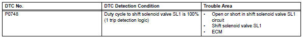
Toyota RAV4 (XA40) 2013-2018 Service Manual: Pressure control solenoid "A" electrical (shift solenoid valve sl1)
Description
Shifting from 1st to o/d is performed in combination with the on and off operation of the shift solenoid valves sl1 and sl2, which are controlled by the ecm. If an open or short circuit occurs in any of the shift solenoid valves, the ecm controls the remaining normal shift solenoid valves to allow the vehicle to be operated safely (see page ax-31).
Monitor description
This dtc indicates an open or short in the shift solenoid valve sl1 circuit. The ecm commands gear shifts by turning the shift solenoid valves on/off. When there is an open or short circuit in any shift solenoid valve circuit, the ecm detects the problem, illuminates the mil and stores the dtc. Also, the ecm performs the fail-safe function and turns the other normal shift solenoid valves on/off. In case of an open or short circuit, the ecm stops sending current to the circuit (see page ax-31).
Monitor strategy
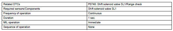
Typical enabling conditions
Typical malfunction thresholds
![]()
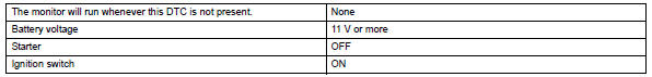
Component operating range
![]()
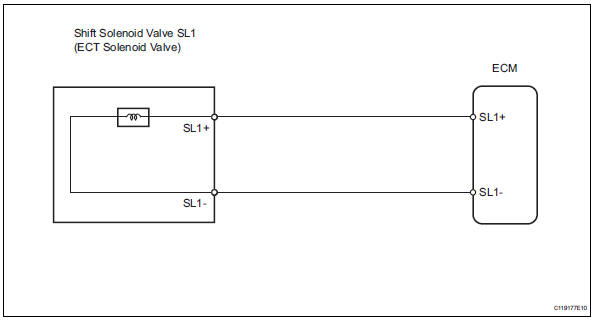
Wiring diagram
Inspection procedure
- Inspect transmission wire (shift solenoid valve sl1)
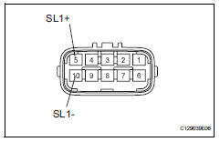
- Disconnect the b27 wire connector.
- Measure the resistance of the transmission wire.
Standard resistance 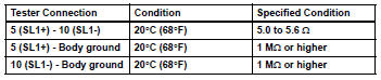


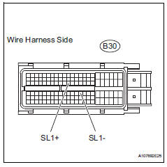
- Check wire harness (transmission wire - ecm)
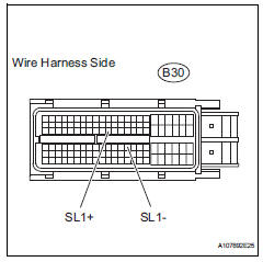
- Disconnect the b30 ecm connector.
- Measure the resistance of the wire harness side connector.
Standard resistance 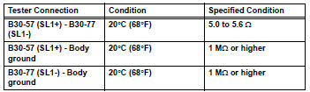

Replace ecm
- Inspect shift solenoid valve sl1
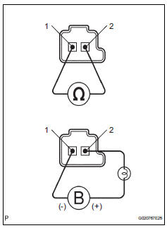
- Remove the shift solenoid valve sl1.
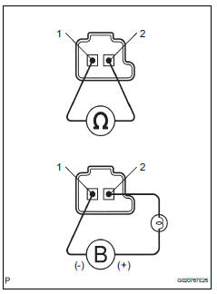
- Measure the resistance of the solenoid valve.
Standard resistance: 5.0 To 5.6 Ùat 20°c (68°f)
- Connect the battery's positive (+) lead with a 21 w bulb to terminal 2 and the negative (-) lead to terminal 1 of the solenoid valve connector. Then check that the valve moves and makes an operating noise.
Ok: valve moves and makes operating noise.

Repair or replace transmission wire
- Check wire harness (transmission wire - ecm)
- Disconnect the b30 ecm connector.
- Measure the resistance of the wire harness side connector.
Standard resistance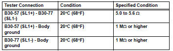

Replace ecm
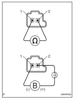
- Inspect shift solenoid valve sl1
- Remove the shift solenoid valve sl1.
- Measure the resistance of the solenoid valve.
Standard resistance: 5.0 To 5.6 Ùat 20°c (68°f)
- Connect the battery's positive (+) lead with a 21 w bulb to terminal 2 and the negative (-) lead to terminal 1 of the solenoid valve connector. Then check that the valve moves and makes an operating noise.
Ok: valve moves and makes operating noise.


Repair or replace transmission wire
 Pressure control solenoid "A " performance (shift solenoid valve sl1)
Description
The ecm uses signals from the vehicle speed sensor to detect the actual gear
position (1st, 2nd, 3rd or
o/d gear).
Then the ecm compares the actual gear with the shift schedule in t ...
 Shift solenoid "d" performance (shift solenoid valve s4)
System description
The ecm uses signals from the output shaft speed sensor and input speed
sensor to detect the actual
gear position (1st, 2nd, 3rd or o/d gear).
Then the ecm compares the a ...
Other materials:
Rear brake
Components
Removal
Hint:
Use the same procedures for the lh side and rh side.
The procedures listed below are for the lh side.
Remove rear wheel
Drain brake fluid
Notice:
Wash off brake fluid immediately if it comes in
contact with any painted surface.
Disconnect rea ...
Programming HomeLink
â– Before programming
HomeLink
During programming, it is possible
that garage doors,
gates, or other devices may
operate. For this reason,
make sure that people and
objects are clear of the
garage door or other devices
to prevent injury or other
potential harm.
It is recommended that a n ...
Disassembly
Remove no. 3 Heater to register duct
Detach the 6 claws and remove the heater to
register duct.
Remove air duct
Detach the 2 claws and remove the air duct.
Remove air outlet control servo motor
Remove the 3 screws.
Detach the evaporator case from the ...
