Toyota RAV4 (XA40) 2013-2018 Service Manual: Problem symptoms table
Hint:
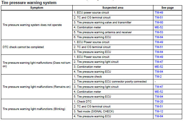
- Use the table below to help determine the cause of the problem symptom. The potential causes of the symptoms are listed in order of probability in the "suspected area" column of the table. Check each symptom by checking the suspected areas in the order they are listed. Replace parts as necessary.
- Inspect the fuses and relays related to this system before inspecting the suspected areas below.
 Test mode procedure
Test mode check
Hint:
When entering the test mode, the tire pressure
warning ecu sets all the test dtcs first. After
completing the test mode for each inspection item, the
dtcs that ar ...
 Terminals of ecu
Check tire pressure warning ecu
Disconnect the e56 ecu connector.
Measure the voltage and resistance of the wire
harness side connector.
If the result is not as specified, ther ...
Other materials:
Fastening and releasing
the seat belt
To fasten the seat belt, push
the plate into the buckle until a click sound is heard.
To release the seat belt,
press the release button A.
â– Emergency locking retractor
(ELR)
The retractor will lock the belt during
a sudden stop or on impact. It may
also lock if you lean forward too
quickly ...
Disposal
Hint:
When scrapping a vehicle equipped with an srs or disposing
of the front passenger side knee airbag, be sure to deploy the
airbag first in accordance with the procedure described
below. If any abnormality occurs with the airbag deployment,
contact the service dept. Of toyota motor sales,
...
High beam automatic turning on or off conditions
When all of the following conditions are fulfilled, high beam will be
automatically turned on:
Vehicle speed is above approximately 21 mph (34 km/h).
The area ahead of the vehicle is dark.
There are no oncoming or preceding vehicles with headlights or tail
lights turned on.
There are fe ...
