Toyota RAV4 (XA40) 2013-2018 Service Manual: Test mode procedure
- Test mode check
Hint:
- When entering the test mode, the tire pressure
warning ecu sets all the test dtcs first. After
completing the test mode for each inspection item, the
dtcs that are determined normal by the tire pressure
warning ecu will be erased.
The dtcs for other inspection items may not be erased when only a certain signal is inspected.
- When the test mode returns back to the normal mode, all the test dtcs will be erased.
- Make sure that the ignition switch is off.
- Connect the intelligent tester (with can vim) to the dlc3.
- Turn the ignition switch on.
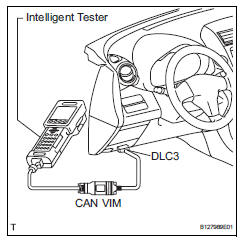
- Select test mode on the intelligent tester.
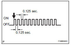
- Confirm that the tire pressure warning light in the combination meter blinks at 0.125 Second intervals.
- Perform signal check
Hint:
- When entering the signal check, the tire pressure
warning ecu sets all the signal check dtcs first.
After completing the signal check for each inspection item, the dtcs that are determined normal by the tire pressure warning ecu will be erased. The dtcs for other inspection items may not be erased when only a certain signal is inspected.
- When the signal check returns back to normal mode, all the signal check dtcs will be erased.
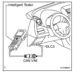
- Make sure that the ignition switch is off.
- Connect the intelligent tester (with can vim ) to the dlc3.
- Turn the ignition switch on.
- Select signal check on the intelligent tester.
- Drive the vehicle at 12 mph (20 km/h) or more for 10 seconds or more
- Loosen the valve core and rapidly reduce the pressure (above 40 kpa / 30 seconds or more).
Hint:
The transmitter id can be transmitted by rapidly reducing the tire pressure.
- Result
Hint:
After the signal check is completed, check for a
dtc and signal check dtc to confirm the system
status.

- End of signal check
After completing test mode (signal check), turn the ignition switch off and disconnect the tester.
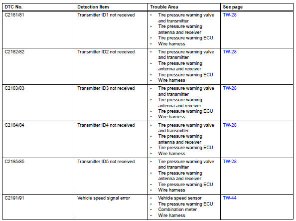
Dtc of signal check (test diagnosis) function: If a malfunction code is displayed during the test mode dtc check, check the circuit listed for that code. For details of each code, refer to the "see page" of the "dtc no." In the chart.
 Registration
In case of tire pressure warning ecu
replacement
Read id stored in the old ecu using the intelligent
tester.
In case of tire pressure warning valve and
transmitter and/or tire pre ...
 Problem symptoms table
Hint:
Use the table below to help determine the cause of the
problem symptom. The potential causes of the symptoms
are listed in order of probability in the "suspected area"
column ...
Other materials:
Blower unit
Components
Removal
Disconnect cable from negative battery
terminal
Caution:
Wait at least 90 seconds after disconnecting the
cable from the negative (-) battery terminal to
prevent airbag and seat belt pretensioner activation.
Remove upper instrument panel
Remove the upper ...
Rear door courtesy switch
Components
Removal
Hint:
Use the same procedures for the rh and lh sides.
The procedures listed below are for the lh side.
Disconnect cable from negative battery
terminal
Caution:
Wait at least 90 seconds after disconnecting the
cable from the negative (-) battery terminal t ...
Diagnosis system
Description
The ecm controls the function of cruise control on this
vehicle. Data of the cruise control or dtc can be read
from the dlc3 of the vehicle. When trouble occurs with
cruise control, check that the cruise main indicator
does not come on but dtc inspection is performed.
Theref ...
