Toyota RAV4 (XA40) 2013-2018 Service Manual: Removal
Hint:
- Use the same procedures for the rh side and lh side.
- The procedures listed below are for the lh side.
- When removing the moulding, heat the vehicle body and moulding using a heat light.
Standard heating temperature 
Notice:
Do not heat the vehicle body and moulding excessively.
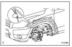
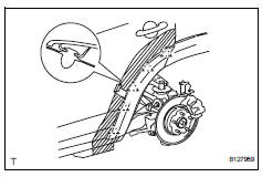
- Remove front fender moulding subassembly lh
- Put protective tape around the moulding.
- Remove the 4 screws and detach the 2 clips.
- Using a moulding remover, detach the 9 clips and remove the moulding.
Notice:
- If reusing the moulding, take care not to damage the moulding.
- Be careful not to damage the vehicle body.
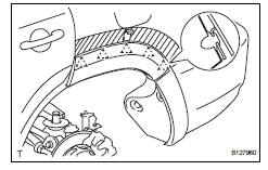
- Remove no. 2 Rear wheel opening extension lh
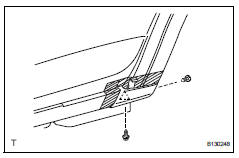
- Put protective tape around the moulding.
- Remove the screw.
- Using a clip remover, detach the 2 clips and remove the extension.
Notice:
- If reusing the extension, take care not to damage the extension.
- Be careful not to damage the vehicle body.
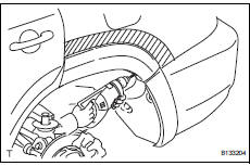
- Remove no. 1 Rear wheel opening extension lh
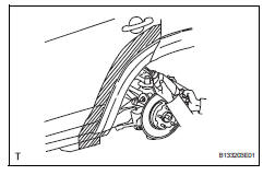
- Put protective tape around the extension.
- Using a drill bit of less than ö 4 mm (0.16 In.), Drill out the 3 rivet flanges.
Hint:
Wind tape around the drill bit approximately 5 mm (0.20 In.) From the tip of the drill.
Notice:
- Do not drill the rivet at an angle as this will cause damage to the drill and drill hole. Line up the drill and rivet, and carefully drill out the rivet head.
- Be careful as the cut rivet will be very hot.
- Continue drilling and push out the remaining rivet fragments using the drill.
- Using a vacuum cleaner, remove the rivet fragments and shavings from the drilled areas.
- Using a heat light, heat the extension and vehicle body.
- Cut the double-sided tape that holds the moulding to the vehicle body with a knife.
Notice:
- If reusing the extension, take care not to damage the extension.
- Be careful not to damage the vehicle body.
- Using a moulding remover, detach the 5 clips and remove the extension.
- Remove rear quarter outside moulding lh
- Put protective tape around the moulding.
- Using a drill bit of less than ö 4 mm (0.16 In.), Drill out the 3 rivet flanges.
Hint:
Wind tape around the drill bit approximately 5 mm (0.20 In.) From the tip of the drill.
Notice:
- Do not drill the rivet at an angle as this will cause damage to the drill and drill hole. Line up the drill and rivet, and carefully drill out the rivet head.
- Be careful as the cut rivet will be very hot.
- Continue drilling and push out the remaining rivet fragments using the drill.
- Using a vacuum cleaner, remove the rivet fragments and shavings from the drilled areas.
- Using a heat light, heat the moulding and vehicle body.
- Using a moulding remover, detach the 5 clips and remove the moulding.
Notice:
- If reusing the moulding, take care not to damage the moulding.
- Be careful not to damage the vehicle body.
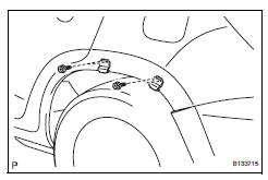
- Remove no. 2 Rocker panel moulding retainer lh
- Remove the 2 screws and retainer.
- Remove quarter opening retainer lh
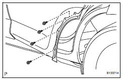
- Remove the 4 screws and retainer.
- Remove no. 1 Rocker panel moulding retainer lh
- Remove the 4 screws and 2 retainers.
 Outside moulding
Components
...
 Installation
Hint:
Use the same procedures for the rh side and lh side.
The procedures listed below are for the lh side.
When installing the moulding, heat the vehicle body and
moulding using a heat ligh ...
Other materials:
Installation
Install starter assembly
Install the starter with the 2 bolts.
Torque: 37 n*m (377 kgf*cm, 27 ft.*Lbf)
Connect the starter connector.
Install the terminal nut and cover the nut with the
cap.
Torque: 9.8 N*m (100 kgf*cm, 7 ft.*Lbf)
Install battery bracket reinfor ...
Headlight (hi-beam) circuit
Description
The body ecu controls the headlight relay, no. 2 Daytime running light relay
(marking: drl no. 2) And
no. 4 Daytime running light relay (marking: drl no. 4).
Wiring diagram
Inspection procedure
Perform active test by intelligent tester
Connect the intelligent test ...
How to proceed with troubleshooting
Hint:
Use the following procedures to troubleshoot the occupant
classification system.
*: Use the intelligent tester.
Vehicle brought to workshop
Passenger airbag on/off indicator check
Dtc check (present and past dtc)*
Check for dtcs (see page rs-249 ).
Result ...
